L18 - Beam Steering#
Beam Steering
The phase each PHASER element needs to steer the beam to a commanded angle, and what the steered beam looks like.
Lesson 18 · Antennas, Phased Arrays, and Radar Systems · Dr. Neil Rogers
Printing
To print the slides, switch to present mode and print: one slide a sheet, with room for notes. Print from read mode for the whole lesson.
Learning Objectives
- I can calculate the phase weights required to steer a beam to a given angle and predict the resulting array pattern.
Lesson 17 put the PHASER in front of you: eight patch elements in a row, two
ADAR1000 beamformer chips that set a phase on every element, and the backend
code that writes the steering ramp i*PhDelta to them. In the GUI, the beam
sweep sets that ramp, and Phase Control adds per-element offsets on top of it. Nothing so far has said what the ramp should be. We derive the
element-to-element phase from the arrival geometry, turn it into the eight
settings the hardware accepts, predict what the steered pattern looks like, and
then read the process backwards — given a set of phases, find the angle the
array is pointing.
Time Alignment
Eight elements in a row, \(d = 14\ \text{mm}\) apart, with no phase applied.
A plane wave from \(\theta_0\) off broadside reaches them one after another, not all at once.
Undoing those arrival differences makes all eight signals add in phase.
Eight elements sit in a row with no phase applied, spaced \(d = 14\ \text{mm}\) apart, and a plane wave arrives from an angle \(\theta_0\) measured from broadside. The wavefront reaches the element nearest the source first and each successive element later.
The widget opens with the steer angle locked to the source, so the commanded delays line all eight signals up and each ADAR1000’s four-element sum adds in phase with the other’s. Clear the lock and move the steer angle away from the source: the delays no longer match the arrival times, the two chip sums part, and the total shrinks.
Path, Time, and Phase
\(\Delta r\) is the extra path between neighbors; element \(n\) sees \(n\) times each quantity.
At \(\theta_0 = 30^\circ\): 7 mm and about 23 ps per element.
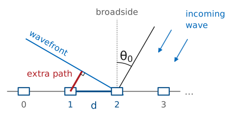
Look at two neighboring elements. The wavefront that has just touched one of them still has to travel a short leg before it touches the other. That leg is one side of a right triangle whose hypotenuse is the element spacing \(d\) and whose angle at the element is \(\theta_0\), so its length is
Element \(n\) sits \(n\) spacings from element 0, so its path runs \(n\ d\sin\theta_0\) shorter — it sees the wave that much sooner.
Dividing the path difference by the speed of light gives the arrival-time difference between neighbors:
For the course array steered to 30°, that is 7 mm of path and about 23 ps of arrival-time difference per element.
Now convert the time offset into a phase. A time offset of \(\Delta t\) at frequency \(f\) shifts a sinusoid’s phase by \(\omega\Delta t\), so the incoming wave produces an element-to-element phase difference of
Element \(n\) receives the wave \(n\ \Delta t\) before element 0, so its signal leads element 0’s by \(n\ \omega\Delta t = n\ \Delta\phi\). To line the eight signals up, the phase shifter on element \(n\) delays it by that same \(n\ \Delta\phi\).
Reading the Progressive Phase
Broadside needs none: all phases at zero point the beam at 0°.
It follows \(\sin\theta_0\): 0° to 10° needs 30.1°, 80° to 90° only 2.6°.
It scales with \(d/\lambda\): a higher frequency needs more phase per element.
This is the progressive phase, and it is the equation the rest of Module 3 runs on. It converts a geometric path difference into an electrical one, and the phase table, the steered pattern, and the inverse problem all follow from it. Read what it says. At broadside, \(\sin\theta_0 = 0\) and no phase is needed, which is why the array points to 0° with every phase set to zero. The phase grows with the sine of the steer angle rather than with the angle, so the same 10° of extra scan needs much less added phase near endfire than it does near broadside: on the course array, steering from 0° to 10° takes 30.1° of added phase per element, and steering from 80° to 90° takes 2.6°. And the phase scales with the electrical spacing \(d/\lambda\): the same array asked to steer the same angle needs more phase per element as the frequency goes up.
Time Delay Versus Phase Delay
A true time delay steers the beam to \(\theta_0\) at every frequency.
A phase shift equals that delay at one frequency only, the one used for \(k\).
Elsewhere the beam points slightly off \(\theta_0\): beam squint, which L23 quantifies.
Note
\(\Delta t\) is a true delay and \(\Delta\phi\) is a phase shift, and the two are equal at exactly one frequency, the one used to compute \(k\). A true time delay would steer the beam to \(\theta_0\) at every frequency in the band; a phase shifter steers it to \(\theta_0\) only at the design frequency and to a slightly different angle everywhere else. That difference has a name, beam squint, and L23 quantifies it. For now, every phase we compute today is correct only at that frequency.
Sign of the Compensating Ramp
Element \(n\) leads element 0 by \(n\ \Delta\phi\); the ADAR1000 delays it by that amount.
A positive ramp steers to \(+\theta_0\), as the GUI’s beam sweep does.
Element 0 sits at zero; a negative \(\theta_0\) runs the ramp downward.
The array’s own geometry gives element \(n\) a phase lead of \(n\ \Delta\phi\) over element 0. To make all eight signals add in phase, the beamformer delays element \(n\) by that same amount. The ADAR1000’s phase setting is a delay, so the phase commanded to element \(n\) is the lead itself:
Element 0 is the reference and gets zero. Each element after it is delayed one
step more. A positive ramp steers the beam to \(+\theta_0\), which is the
convention of the backend code L17 read, which writes i*PhDelta to element
i at every step of the GUI’s beam sweep. The GUI’s Beam Steering Apply is
a different control: it writes the opposite ramp into Phase Control as offsets,
for a reason the L18 Lab explains. Flipping the sign of \(\theta_0\) flips the
sign of \(\Delta\phi\) and runs the ramp the other way, which is how the same
eight channels cover both sides of broadside.
L16 wrote the same steering as a complex weight, \(a_n = \vert a_n\vert\ e^{-jn\beta}\) with \(\beta = \Delta\phi\). A delay of \(n\ \Delta\phi\) multiplies element \(n\)’s signal by \(e^{-jn\Delta\phi}\), so the weight carries a minus sign that the setting does not. That weight phase is the one place \(-n\ \Delta\phi\) survives; every phase setting in this lesson and in the lab is \(+n\ \Delta\phi\).
Receive Signal Path
This is the same array on receive, followed down its signal lines. Nothing in front of the array points anywhere: the wave from \(\theta_s\) simply arrives, and it reaches element \(n\) with a lead of \(n\ kd\sin\theta_s\) over element 0, so the eight received signals come in staggered. Each element turns whatever reaches it into a signal on its line, from any direction. The steering happens behind the elements. Inside each ADAR1000, every line passes through a phase shifter set to \(n\ \Delta\phi\) (the box shows the setting, wrapped to 0° to 360° as the chip holds it) and then a gain stage, and the chip sums its four lines. The two chip sums reach the Pluto as separate channels, and the software adds them. \(\theta_0\) is nothing but those delays: moving it changes the boxes and everything after them, and nothing in the field.
Lock the delays to the source and they cancel the leads: the shifted waves line up crest to crest, each chip sum is four times one element, and the total reaches 8. Clear the lock and move \(\theta_0\): the shifted waves fan out and the sums shrink. Turn on the 2nd source and a second wave, from \(\theta_2\), reaches the same elements; each line carries both, drawn apart in two colors. The same delays that line up the first scramble the second, so the total keeps one and loses the other: at the default settings, 8 against 0.72, or −21.0 dB. That is the receive pattern, built by the delays, not by anything in space. Step walks the chain one stage at a time. The gain stage is where L22 applies a taper; leave it at uniform for now, or pick Hann to see the aligned total fall from 8 to 4.64.
Phase Swings the Fringes
This is the two-element pair from L16 with a phase setting on the right-hand element. The spacing is \(\lambda/2\) and the elements are isotropic, so at \(\Delta\phi = 0^\circ\) the two fields add at broadside and cancel along the array axis. Sweep the phase. Delaying the right element by \(\Delta\phi\) holds back the wave that reaches the right side first, so the fringes swing toward it and the beam lands where \(\sin\theta_0 = \Delta\phi/kd\): 30° at \(\Delta\phi = 90^\circ\) and 90° at 180°. A negative setting swings it the other way. Widen the spacing to \(2\lambda\) and every lobe swings together, grating lobes included: the phase moves the whole interference pattern, which is the rigid shift in sine space later in this lesson.
The Phaser Kit (CN0566)
At 10.3 GHz with \(d = 14\ \text{mm}\): \(\lambda = 29.1\ \text{mm}\) and \(d/\lambda = 0.481\).
One number, \(kd\), sets \(\Delta\phi\) for every steer angle on this array.
For the course array at the workshop frequency, \(\lambda = 29.1\ \text{mm}\), \(d/\lambda = 0.481\), and
Multiplying \(kd\) by \(\sin\theta_0\) gives \(\Delta\phi\) for any steer angle on this array.
The eight elements sit on two ADAR1000s, elements 0 to 3 on one and 4 to 7 on the other, and each chip sums its four into one channel; L17’s “The Hybrid Beamformer” adds the two channels digitally. The ramp continues across the chip boundary, so \(\phi_4 = 4\ \Delta\phi\) is set on the second chip. It steers the whole array only if the two subarray channels are phase-matched where they are summed. The GUI’s Calibrate step measures each element’s phase against its neighbor, including the element 3 and 4 pair that spans the two chips, so the mismatch between the subarrays is folded into the offsets of elements 4 to 7.
Worked Example: Phase Table at 30°
\(n\) |
0 |
1 |
2 |
3 |
|---|---|---|---|---|
set |
0 |
86.6 |
173.2 |
259.8 |
\(n\) |
4 |
5 |
6 |
7 |
set |
346.4 |
73.0 |
159.6 |
246.2 |
Whole turns wrap each \(n(86.6^\circ)\) into 0° to 360°: 433.0° becomes 73.0°.
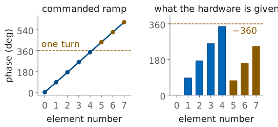
Worked example — the phase table for \(\theta_0 = 30^\circ\)
At 10.3 GHz with \(d = 14\ \text{mm}\):
Element \(n\) is commanded to \(n(86.6^\circ)\). The ADAR1000 accepts a phase in 0° to 360°, so each value is wrapped by subtracting whole turns until it lands in that range.
\(n\) |
0 |
1 |
2 |
3 |
4 |
5 |
6 |
7 |
|---|---|---|---|---|---|---|---|---|
\(\phi_n\) (ramp) |
0 |
86.6 |
173.2 |
259.8 |
346.4 |
433.0 |
519.6 |
606.2 |
turns removed |
0 |
0 |
0 |
0 |
0 |
−360 |
−360 |
−360 |
\(\phi_n\) (set) |
0 |
86.6 |
173.2 |
259.8 |
346.4 |
73.0 |
159.6 |
246.2 |
The bottom row is what goes into the hardware. It climbs to element 4, drops back by a turn, and climbs again, a sawtooth rather than a single ramp, and it is correct: a phase of 433.0° and a phase of 73.0° produce the same field from that element.
Phase Wrapping and True Delay
At one frequency, 360° is the same as 0°: 433.0° and 73.0° steer the same beam.
The wrapped table loses the record of the true delay.
So wideband systems use time-delay units instead of, or alongside, phase shifters.
Wrapping discards whole turns. At a single frequency a phase of 360° is the same as 0°, so nothing is lost: element 5 set to 73.0° radiates exactly as it would at 433.0°. What the wrapped table does lose is the record of the true delay, which is the reason a wideband system uses time-delay units instead of, or alongside, phase shifters.
The Steered Pattern
Element \(n\) arrives with phase \(n\ kd\sin\theta\); its delay subtracts \(n\ \Delta\phi\).
\(\Delta\phi\) is L16’s \(\beta\): the function is unchanged, only its argument.
The peak at \(\psi = 0\) now means \(\sin\theta = \sin\theta_0\): the beam points at \(\theta_0\).
L16 built the array factor for a uniform line of \(N\) elements with a progressive phase between them. With the ramp \(\phi_n = n\ \Delta\phi\) set as a delay, element \(n\) contributes a propagation phase \(n\ kd\sin\theta\) and its delay takes away \(n\ \Delta\phi\), so the array-factor argument becomes
The \(\Delta\phi\) here is the \(\beta\) of L16’s steering phase. The function is unchanged; only its argument has shifted. The peak still sits at \(\psi = 0\), which now means \(\sin\theta = \sin\theta_0\), so the main lobe points at the commanded angle.
Rigid Shift in Sine Space
Against \(\sin\theta\) the pattern slides unchanged; against \(\theta\) it stretches as it moves.
At 30°, \(\lambda/Nd = 0.260\): nulls at 13.9° and 49.5°, 16.1° and 19.5° from the peak, wider toward endfire.
The upper \(m = 2\) null would need \(\sin\theta = 1.020\): no real angle.
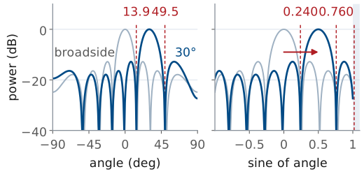
Every other feature of the pattern moves with it, but rigidly in \(\sin\theta\), not in \(\theta\). Plot the pattern against \(\sin\theta\) and steering slides the whole curve sideways without changing its shape. Plot it against \(\theta\) and the same curve stretches as it moves, which is the beam broadening derived in “Beam Broadening” below.
The nulls follow the same substitution. \(AF_N\) vanishes when \(N\psi/2\) is a nonzero multiple of \(\pi\), so
At a multiple of \(N\) the numerator and the denominator vanish together, and that point is a grating lobe, not a null. L16’s “Grating Lobes” puts the first one at \(\sin\theta_g = \sin\theta_0 - \lambda/d\) and keeps it out of real space while \(d < \lambda/(1 + \vert\sin\theta_0\vert)\). Steered to 30°, the course array would need \(d > 19.4\ \text{mm}\) for one to appear, and a full 90° scan needs only \(d < 14.55\ \text{mm}\), so the PHASER’s 14 mm never shows one: at 30° the lobe would sit at \(\sin\theta = -1.58\).
For the course array, \(\lambda/Nd = 29.1/112 = 0.260\). Steered to 30°, the two nulls flanking the main lobe are at \(\sin\theta = 0.240\) and \(\sin\theta = 0.760\), or 13.9° and 49.5°. They are no longer symmetric about the beam: the main lobe reaches 16.1° below the peak and 19.5° above it, wider toward endfire. The nulls are an equal step of 0.260 apart in \(\sin\theta\), and a fixed step in \(\sin\theta\) is a larger step in \(\theta\) where \(\cos\theta\) is small, since \(d\theta = d(\sin\theta)/\cos\theta\). The \(m = 2\) null on the upper side would need \(\sin\theta = 1.020\), which no real angle satisfies, so that null has left the visible region (L16, “Part 4: The Visible Region”) entirely.
Phase Ramp and Beam
Use the widget below to connect the two halves of the lesson. Drag the steer angle and watch the eight commanded phases and the main lobe move together, then switch the phase display between the wrapped values and the unwrapped ramp — the sawtooth is the same physics as the straight line. Switch the x axis to sine and the lobe slides along it without changing shape, by 0.500 at 30°, the rigid shift of the frame before. Set \(\theta_0 = 30^\circ\) and check the bars against the worked table above: a positive steer angle gives a rising ramp. Then scan out toward 60° and compare the −3 dB width printed on the pattern, which is read off the exact array factor, with the HPBW readout, which is the \(1/\cos\theta_0\) rule: at 60° the rule gives 26.4° and the pattern 30.5°.
Beam Broadening
Steering widens the beam: a source at \(\theta_0\) sees the array’s projection, shorter by \(\cos\theta_0\).
L15’s uniform-aperture beamwidth, in radians, with the projected length.
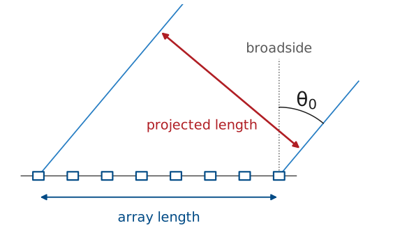
Steering widens the beam because a source at \(\theta_0\) sees the array’s projection onto the plane perpendicular to its line of sight, which is shorter than the array by \(\cos\theta_0\).
The length that matters is \(Nd = 112\ \text{mm}\), not the 98 mm between the centers of the first and last elements. L16’s “Part 5: The Array as a Sampled Aperture” treats the array as a line source sampled every \(d\), so each element stands for a cell \(d\) wide and the eight cells fill an equivalent aperture \(Nd = 3.85\lambda\). Using 98 mm would give 15.1° at broadside instead of 13.2°, against 13.3° read off the exact array factor. The effective aperture length is therefore
L15 gave the half-power beamwidth of a uniform aperture of length \(L\) as
which for the course array at broadside is \(0.886(29.1)/112 = 0.2302\ \text{rad} = 13.2^\circ\). Substituting the projected length,
Scan Loss
The smaller projected aperture lowers the peak gain: −3 dB at 60°.
The array factor’s directivity holds near 7.7 as it scans; the element pattern carries the loss.
L21 works out the element factor and the scanned gain.
The beam broadens as \(1/\cos\theta_0\). The same projection argument sets the scan loss in gain: the aperture the array presents to a source at \(\theta_0\) is smaller by \(\cos\theta_0\), so the peak gain drops by
The array factor alone barely changes its directivity as it scans. For isotropic elements it computes to 7.70 at broadside, 7.70 at 30°, 7.78 at 45°, and 8.16 at 60°, a slight rise. A linear array’s beam is a cone around the array axis, not a pencil. Steering tilts that cone toward the axis: its circumference shrinks as \(\cos\theta_0\) while its width in \(\theta\) grows as \(1/\cos\theta_0\), so the solid angle the beam fills, and with it the directivity, stays about the same. The element pattern, which is not isotropic and rolls off away from its own boresight, carries the projected-aperture loss: each element’s cell presents a projected area that shrinks as \(\cos\theta\). L21 derives the element factor and the scanned gain; for design estimates, we use the scan loss above.
Broadening and Scan Loss Versus Angle
\(\theta_0\) |
\(\cos\theta_0\) |
HPBW |
Gain relative to broadside |
|---|---|---|---|
0° |
1.000 |
13.2° |
reference |
30° |
0.866 |
15.2° |
−0.6 dB |
45° |
0.707 |
18.7° |
−1.5 dB |
60° |
0.500 |
26.4° |
−3.0 dB |
Exact width at 60° is 30.5°: the rule reads narrow past 50° of scan.
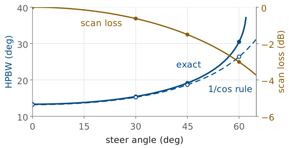
Because the beam broadens and the peak gain falls as the array scans, designers specify a scanned array over a limited field of view: at 60° the PHASER’s beam is twice as wide as at broadside by the rule (2.3 times, exactly), its peak gain is 3 dB lower, and scanning further adds little coverage.
Note
The \(1/\cos\theta_0\) rule is an approximation, and it reads slightly narrow at large scan angles. Measuring the −3 dB width directly off the array factor for this array gives 13.3° at broadside and 19.1° at 45°, both within a few tenths of the rule, but 30.5° at 60° against the rule’s 26.4°. Use the rule for design estimates out to about 50° and the pattern itself past that.
The Inverse Problem
Difference neighboring elements: \(\phi_{n+1} - \phi_n\).
Unwrap. Add or subtract 360° from any difference that disagrees with the others until all seven agree.
That common step is \(\Delta\phi\).
Solve for \(\sin\theta_0\) and take the arcsine:
\[\sin\theta_0 = \frac{\Delta\phi}{kd}\]
The lab hands you the opposite problem. The GUI, or a data file, gives you eight phases, and you have to say where the beam is pointing. Everything you need is in \(\phi_n = n\ \Delta\phi\), run in reverse:
Worked Example: Recovering the Steer Angle
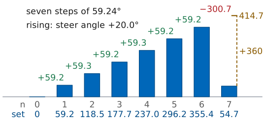
Unwrapped, \(\phi_7 = 414.7^\circ\): seven steps of 59.24°.
Rising ramp: positive \(\Delta\phi\), positive steer angle.
Worked example — recovering the steer angle
The beamformer reports these settings:
\(n\) |
0 |
1 |
2 |
3 |
4 |
5 |
6 |
7 |
|---|---|---|---|---|---|---|---|---|
\(\phi_n\) (deg) |
0 |
59.2 |
118.5 |
177.7 |
237.0 |
296.2 |
355.4 |
54.7 |
The first six differences are 59.2°, 59.3°, 59.2°, 59.3°, 59.2°, and 59.2°. The seventh is \(54.7 - 355.4 = -300.7^\circ\), which is 59.3° once a full turn is restored. All seven agree to within the 0.1° rounding of the table, so the ramp is uniform. The span of the whole array gives the step most precisely: element 7 sits at \(54.7^\circ + 360^\circ = 414.7^\circ\) unwrapped, seven steps from element 0, so
The ramp rises with \(n\) and the steer angle is positive, which follows from the sign convention: the commanded phase is \(+n\ \Delta\phi\), so a rising ramp means a positive \(\Delta\phi\) and a beam on the positive side of broadside, the side the GUI’s sweep plot calls positive.
Two Sanity Checks
Seven differences that cannot be made to agree: no uniform steering ramp. Look for a calibration offset or a bad readout.
\(\vert\Delta\phi/kd\vert > 1\): no real angle fits, so suspect an arithmetic or unit error.
Two checks catch most errors. If the seven differences cannot be made to agree, the array is not carrying a uniform steering ramp: it may include a per-element calibration offset, or the readout may not reflect the commanded phases. Where the odd difference sits says which. An offset \(\delta\) on an interior element spoils the two differences on either side of it, one by \(+\delta\) and the next by \(-\delta\). A single odd difference therefore points to an end element, 0 or 7, or to the step from element 3 to element 4, where the ramp crosses from one ADAR1000 to the other: a phase error between the two subarray channels moves elements 4 to 7 together, which is what the GUI’s Calibrate step measures and removes. And if \(\vert\Delta\phi/kd\vert\) comes out greater than 1, no real angle produces that ramp, which points at an arithmetic or unit error.
Phase-Shifter Resolution
The ADAR1000’s phase shifter has 7 bits, so every commanded phase rounds to this grid.
At 30°, the 86.6° step is set as 31 steps, 87.19°.
L23 computes the effect on sidelobe level and null depth.
The ADAR1000’s phase shifter has 7 bits (L17, “The ADAR1000 Beamformers”), so its smallest step is \(360^\circ/128 = 2.8125^\circ\) and every commanded phase lands on that grid. The 86.6° step of the 30° table is 30.79 steps and is set as 31 steps, 87.19°. The backend rounds each element’s unwrapped ramp value to the grid before wrapping, so the whole 30° ramp is set as 0, 87.19, 174.38, 258.75, 345.94, 73.13, 160.31, and 247.50°. L23 computes how much that grid raises the sidelobe level and reduces null depth.
Summary: Phase Ramp
Symbol / idea |
What it is |
Number to remember |
|---|---|---|
\(\Delta\phi = kd\sin\theta_0\) |
progressive element-to-element phase |
\(173.2^\circ \times \sin\theta_0\) for the course array |
\(\phi_n = +n\ \Delta\phi\) |
commanded ramp (a delay), element \(n\) |
86.6° per element at \(\theta_0 = 30^\circ\) |
wrapping |
whole turns removed to fit 0° to 360° |
433.0° is set as 73.0° |
Summary: Steered Pattern
Symbol / idea |
What it is |
Number to remember |
|---|---|---|
\(\psi = kd(\sin\theta - \sin\theta_0)\) |
array-factor argument |
peak where \(\psi = 0\), so \(\theta = \theta_0\) |
\(\sin\theta_{\text{null}} = \sin\theta_0 \pm m\lambda/Nd\) |
null locations |
\(\lambda/Nd = 0.260\); nulls at 13.9° and 49.5° for \(\theta_0 = 30^\circ\) |
Summary: Broadening and Hardware
Symbol / idea |
What it is |
Number to remember |
|---|---|---|
\(\theta_{\text{HP}} \approx \theta_{\text{HP}}(0)/\cos\theta_0\) |
beam broadening |
\(13.2^\circ \to 18.7^\circ\) at 45°, 26.4° at 60° |
scan loss |
peak gain falls as \(\cos\theta_0\), carried by the element pattern |
−3 dB at \(\theta_0 = 60^\circ\) |
LSB \(= 360^\circ/2^B\) |
phase-shifter step |
2.8125° for the ADAR1000’s 7 bits |
Practice
This lesson’s problems are the pre-lab for the L18 Lab: Part 1 of its packet, completed on your own before the lab period.
Looking Ahead
The L18 Lab: steer the PHASER, sweep, and compare the peak and beamwidth with the prediction.
The lab redoes the 30° table at the HB100’s 10.525 GHz: 88.4° per element, E1 to E8.
L20-L23: beamwidth, tapering, grating lobes, squint, and quantization.
The L18 Lab puts this on the hardware. You will load the Steering Angle lab preset, steer the peak by moving the source and by applying a steer angle, sweep, and compare the measured peak against the prediction. The lab redoes this lesson’s calculation at the HB100’s 10.525 GHz, where \(\lambda = 28.5\ \text{mm}\), \(kd = 176.8^\circ\), and the 30° beam needs 88.4° per element; the GUI numbers the elements E1 to E8, so this lesson’s \(n = 0\) to 7 are E1 to E8. Bring this lesson’s phase table and its HPBW table, because the sweep measures beamwidth as well as peak position and the comparison only means something if the prediction was written down first.
Further out, the ideal steered pattern of this lesson starts to fray. L20 and its lab measure beamwidth against theory across element counts, L22 trades sidelobe level for beamwidth with a taper, and L23 collects the three ways a real steered array departs from today’s result: grating lobes when the spacing is too wide (L16’s criterion, which the PHASER’s 14 mm meets at every angle), beam squint when the frequency moves off the one you designed for, and quantization when the ideal ramp has to land on the 2.8125° grid. Read the L18 Lab procedure before you go to the bench.