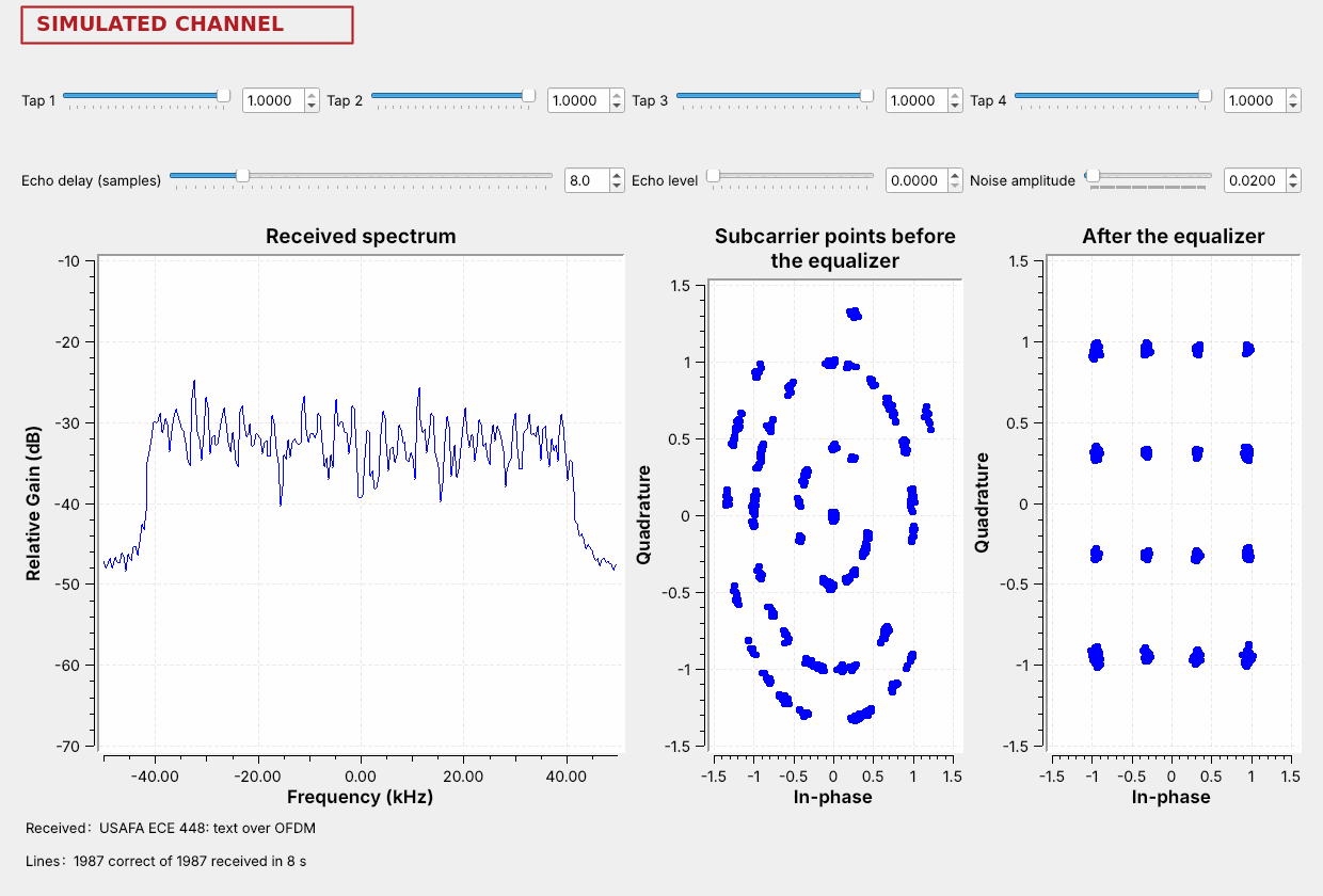
 48 data subcarriers carry 16-QAM, and the text arrives.
Note:
Run L20-ofdm-link.grc live. The left plot is the spectrum of all 52 subcarriers, 48 for data and 4 pilots. The middle plot is the subcarrier points straight out of the receiver's FFT; the right plot is after the equalizer.
---
## From PSK to QAM
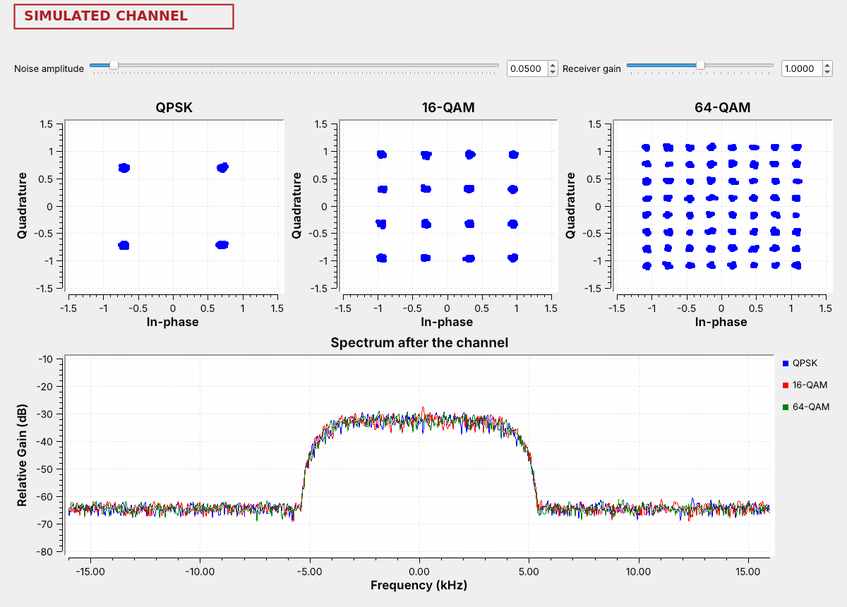 QAM sets amplitude and phase: 16 points carry 4 bits, 64 points carry 6, in the same band.
Note:
Each modulation runs at 8,000 symbols per second through the RRC filter with alpha 0.35, so all three fill 10.8 kHz. 16-QAM carries twice QPSK's bits and 64-QAM three times. On a QAM grid each point's decision region is the square around it.
---
## Bits per Symbol
| | Bits | Bit rate | Point spacing |
| :-- | :-: | :-: | :-: |
| QPSK | 2 | 16 kb/s | 1.41 |
| 16-QAM | 4 | 32 kb/s | 0.63 |
| 64-QAM | 6 | 48 kb/s | 0.31 |
| 256-QAM | 8 | 64 kb/s | 0.15 |
All four run at 8,000 symbols per second in the same 10.8 kHz and at the same average power.
Note:
Each step adds 2 bits per symbol and roughly halves the spacing. The flowgraph's constellation objects are all set to an average power of 1.
---
## The QAM Flowgraph
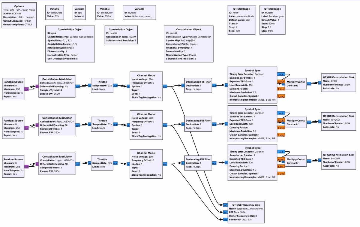 A **Constellation Object** holds the points; the **Constellation Modulator** maps and shapes.
Note:
16-QAM is built in. QPSK and 64-QAM list their points and use power normalization. The receiver is Lesson 15's matched filter and Symbol Sync. One noise slider drives all three Channel Models.
---
## Noise on QAM
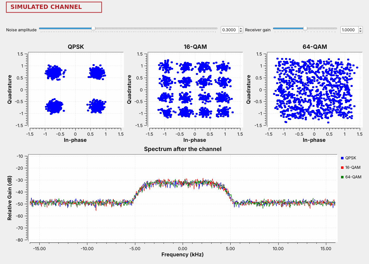 The same noise makes the same clouds; 64-QAM's points merge first.
Note:
Raise the slider from 0.05 to 0.3 live. More points carry more bits in the same band but need a cleaner signal. PySDR's Digital Modulation chapter runs the same comparison.
---
## QAM Explorer
- Start with 16-QAM at noise 0.1.
- Raise the noise until the text breaks, then switch to 64-QAM and 256-QAM.
↗ Interactive on the lesson page
Note: The explorer's noise slider matches the flowgraph's. Wrong decisions and wrong characters are red. --- ## Setting the Level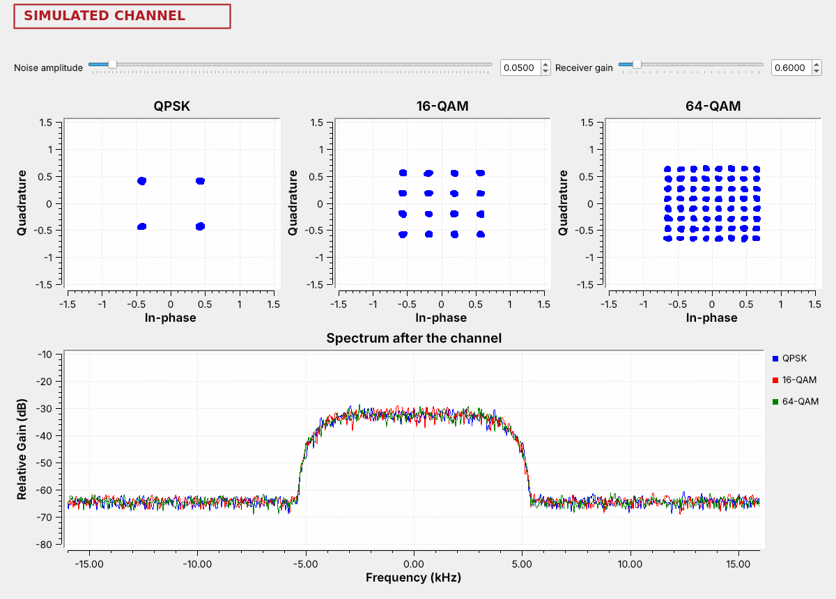 At a gain of 0.6, 16-QAM's outer points sit where its inner points belong; an **AGC** holds the level.
Note:
Move the Receiver gain slider live. QPSK still decodes by quadrant. 16-QAM's outer points move from 0.95 to about 0.57, inside the 0.63 lines between outer and inner points. Amplifiers must stay out of compression, which squeezes the outer points. Carrier recovery for QAM uses the Constellation Receiver block instead of the Costas Loop.
---
## From One Carrier to Many
- **OFDM** sends many slow subcarriers instead of one fast carrier.
- Each carries one point per OFDM symbol.
- An inverse FFT builds the symbol; an FFT separates the subcarriers.
Note:
Lesson 14 met these blocks in HD Radio: OFDM Carrier Allocator, FFT, OFDM Cyclic Prefixer. Long symbols mean an echo smears only a small part of each one, and the guard absorbs that part.
---
## The OFDM Flowgraph
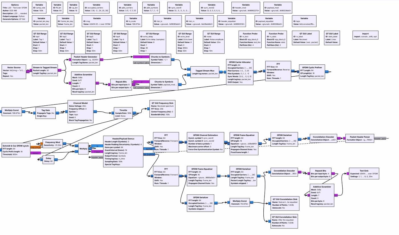 The link uses a 64-point FFT and a 16-sample guard, with 48 data and 4 pilot subcarriers 1,562.5 Hz apart.
Note:
The transmitter is tx_ofdm.grc with 16-QAM; the receiver is rx_ofdm.grc. Schmidl and Cox finds each packet from the first preamble symbol; the second preamble gives the channel estimate; the Frame Equalizer divides each subcarrier by its gain and turns it back by its phase.
---
## The Guard
The guard copies the end of each symbol, so an echo shorter than the guard keeps symbol 1 out of symbol 2's FFT window.
Note:
The window holds symbol 2 from both paths; on each subcarrier that sum is one point with a new gain and phase. An echo longer than the guard puts part of symbol 1 in symbol 2's window, and nothing removes that. The flowgraph's guard is 16 samples, 160 microseconds.
---
## Lesson 15's Taps on OFDM
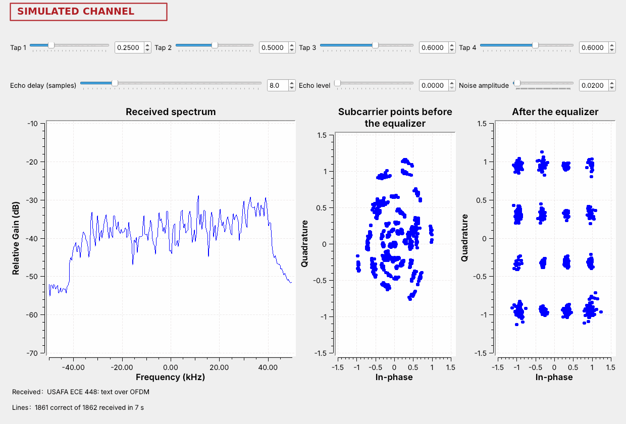 The spectrum tilts; one gain and phase per subcarrier restores the grid.
Note:
At 100 kS/s Tap 1 now sets the lower edge, at minus 40 kHz, so the tilt is steeper than in Lesson 15, which needed an adaptive filter for the same tap settings on one carrier. The weakest subcarriers come out noisier, because the equalizer amplifies their noise too; at noise 0.05 the weak edge corrupts about half the lines.
---
## An Echo Inside the Guard
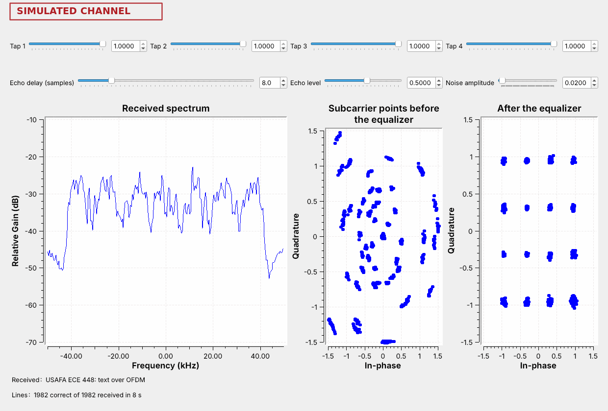 An echo 8 samples late ripples the spectrum, and every line still arrives.
Note:
The ripple repeats every 12.5 kHz, eight times across the window. Each subcarrier sees a fixed gain and phase, which the equalizer removes.
---
## An Echo Past the Guard
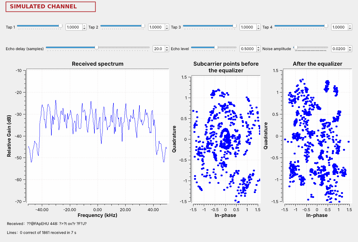 At 20 samples the echo reaches into the next symbol's FFT window, and the grid scatters.
Note:
The text survives echoes up to about 9 samples and fails by about 12, not 16, because the receiver starts its FFT window about 7 samples before the end of the guard as a margin for its own timing. Step the delay up from 8 one sample at a time.
---
## Systems That Use Each One
| System | Subcarriers carry | Guard |
| :-- | :-- | :-- |
| Wi-Fi | BPSK to 4096-QAM | 0.4 to 3.2 µs |
| LTE downlink | QPSK to 256-QAM | 4.7 µs |
| DVB-T TV | QPSK to 64-QAM | up to 224 µs |
| HD Radio | QPSK | 0.15 ms |
Cable TV, cable modems, and microwave links use single-carrier QAM.
Note:
802.11a/g Wi-Fi uses today's subcarrier layout at 20 MS/s: 312.5 kHz apart. LTE uses 15 kHz, and 5G NR uses 15 kHz or a multiple of it. ATSC 3.0, the newer US TV standard, is OFDM too. Cable carries 64- and 256-QAM in 6 MHz channels, and DOCSIS 3.1 moved to OFDM.
---
## Choosing a Scheme
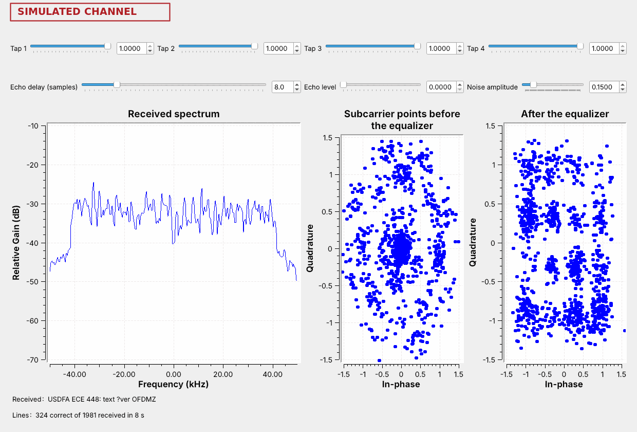 Echoes choose OFDM; noise chooses how many points.
Note:
Wi-Fi and LTE step from 64-QAM down to 16-QAM and QPSK as the signal weakens, adding error-correcting code: PySDR calls these modulation and coding schemes. HD Radio stays with QPSK to reach the edge of coverage.
---
## On the SDR
- `L20-band-pluto.grc` at 2 MS/s near 100 MHz: an FM station with Lesson 14's HD Radio shelves.
- At 20 MS/s on 2.437 GHz: Wi-Fi as flat-topped bursts about 17 MHz wide.
- At 20 MS/s between 729 and 756 MHz: LTE as a flat band about 9 MHz wide that stays on.
Note:
The flowgraph is a PlutoSDR Source with a center frequency control and a 2 or 20 MS/s choice. A Pluto streams about 4 MS/s continuously over USB 2.0; at 20 MS/s each 131,072-sample buffer, 6.5 ms, is unbroken, with samples lost between buffers, and that is enough for the spectrum's shape. At 2 MS/s LTE shows only a flat slice; step 2 MHz to find its edges. Some beacons use the older 802.11b format and look rounded. Look at the spectrum only; nothing here transmits.
---
## Key Point