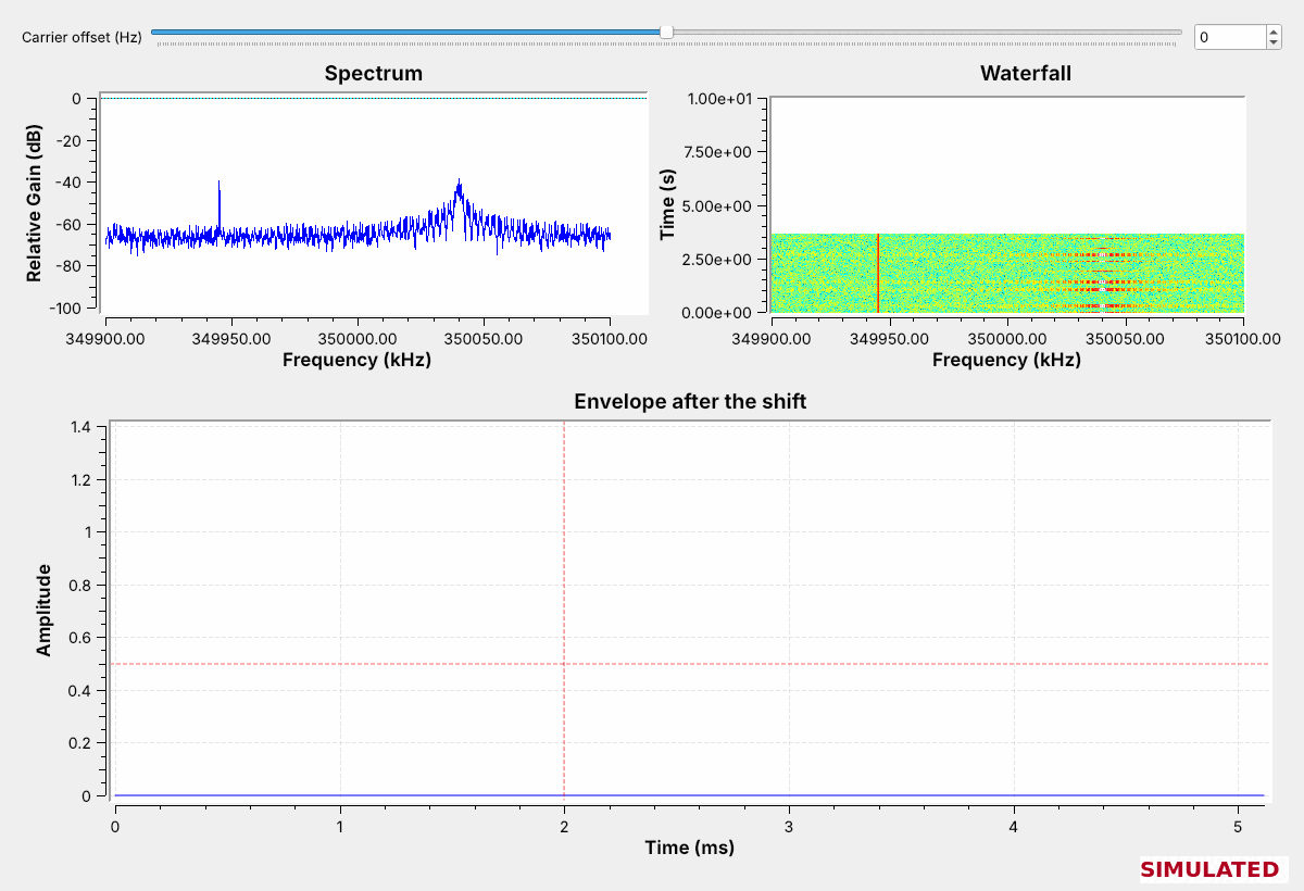
 The steady line never changes; the remote is the one that bursts.
Note:
Let the recording loop and point at the waterfall. The bursts come five times per 2.4 s loop, once per button. A real band has many steady carriers; the waterfall tells us which signal starts and stops with a button press.
---
## Step 1: Shift to 0 Hz
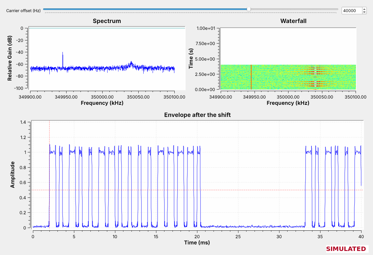 At a 40 kHz offset the envelope fills with pulses: 350.040 MHz.
Note:
The Frequency Xlating FIR Filter shifts the offset to 0 Hz and keeps plus and minus 10 kHz; Complex to Mag gives the envelope. Move the slider 10 kHz off and the pulses drop to half height; 20 kHz off and they disappear. This replaces the live-spectrum fine-tuning from 2025.
---
## Explore: The Live Band on the PlutoSDR
1. Run `L17-explore-pluto.grc` at 433.72 MHz and watch the waterfall.
2. Step the center frequency to find bursts that start and stop.
3. Retune near 315 MHz and look again.
Note:
L17-explore-pluto.grc is L17-capture.grc without the SigMF Sink: a PlutoSDR Source at 2 MS/s with a center frequency you change while it runs. 433.72 MHz keeps the Pluto's DC spike 200 kHz off 433.92 MHz; the course Plutos tune from 70 MHz to 6 GHz, so 315 MHz is in range. Steady lines are carriers; remotes, doorbells, and weather sensors paint short streaks, and sensors send on their own about once a minute. Lower the RX gain if the whole spectrum jumps. SDR Flex is an optional quick look; nothing needs it.
---
## Capture a Real Remote
- Record a real 315 or 433.92 MHz key fob, doorbell, or sensor to SigMF.
- Hold a button down and read its carrier off the spectrum, as in 2025.
- Your Pluto only receives.
Note:
Find the device with L17-explore-pluto.grc, then run L17-capture.grc with fc set about 200 kHz below it before it starts, because the SigMF Sink writes the center frequency when the flowgraph starts. Record each button. A car key fob usually sends a rolling code, so its frames change from press to press.
---
## Step 2: Identify the Modulation
- The envelope has two levels, and the waterfall shows one frequency.
- That is on-off keying (OOK), Lesson 12's keyed carrier switched by a circuit.
Note:
FSK would show two tracks, as in Lesson 8; PSK would stay on at constant amplitude, as in Lesson 15. OOK is one oscillator and one switch, which is why simple remotes, doorbells, and sensors use it.
---
## SigID: Name the Signal
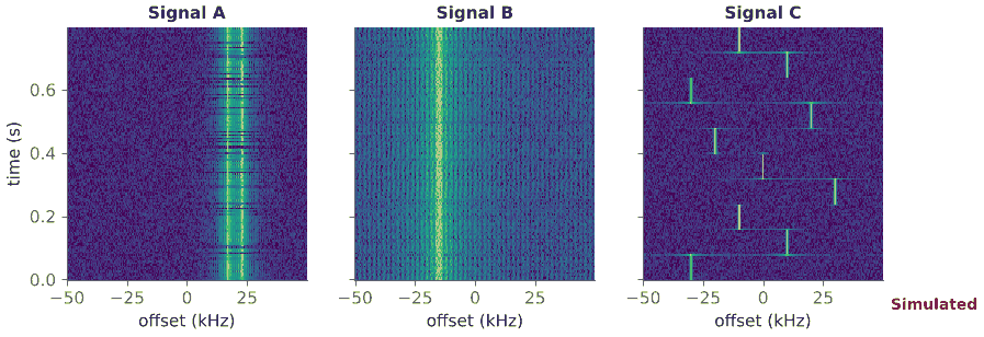 Open `L17-sigid-a`, `-b`, and `-c` in the viewer and name each modulation.
Note:
The 2025 SigID exercise. Set samp_rate to 100000 and fc to 915e6. A is two-level FSK, as in Lesson 8. B is QPSK, one steady band, as in Lesson 15. C is a frequency hopper, as in Lesson 16; the faint horizontal lines are FFT frames that straddle a hop.
---
## Step 3: Read the Chips
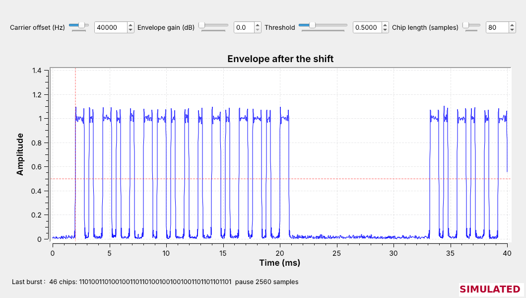 The shortest pulse is 400 µs, 80 samples: set the chip length to 80.
Note:
L17-chips.grc is the viewer's shift and Complex to Mag, then Add Const of minus the threshold, a Binary Slicer, and the Chip Reader, an Embedded Python Block. It keeps the middle sample of each chip, as a Keep 1 in N of 80 would, but starts counting at each burst's first rising edge, and prints one line of chips per burst with the pause after it.
---
## Step 3: Chips to Bits
The fan remote's chips come in threes: `110` is a 1 and `100` is a 0.
Note:
That is pulse-width coding: every bit starts on, and a 1 stays on longer. The other two rows are common too: pulse distance, where the gap carries the bit, and Manchester, where every bit has a mid-bit transition. The Chip Reader prints 46 or 47 chips, not 48, because the last off chips run into the pause.
---
## Step 3: The Fields
| Light | Fan Off | Low | Medium | High |
| :-: | :-: | :-: | :-: | :-: |
| 0xA61E | 0xA62D | 0xA63C | 0xA64B | 0xA65A |
Note:
The first byte never changes: the address. The third nibble counts up with the buttons: the command. The last nibble is the command inverted: a check. Each press sends the frame 6 times with about 12 ms between frames.
---
## Bit Rate and Baud Rate
$$\begin{aligned}
\text{chip} &= 80 / 200{,}000 = 400\ \mu\text{s} \\
\text{baud rate} &= 2500\ \text{baud} \\
\text{bit rate} &= 2500 / 3 = 833\ \text{bits/s}
\end{aligned}$$
A frame of 16 bits takes 19.2 ms, and one starts every 31.2 ms.
Note:
The Chip Reader keeps one sample per chip, so it works at the baud rate. Three chips make one bit. These are the encoder's numbers: chip_len for the Repeat and the gap for the Stream Mux.
---
## Pulse Decoder Explorer
- Find the chip length that leaves no `?` groups.
- Pick another button and read its command.
- Raise the noise and watch the groups break.
↗ Interactive on the lesson page
Note: It opens at 300 microseconds, which is wrong. At 400 every group is 110 or 100. Noise up to about 0.4 reads cleanly; from about 0.45 groups break into question marks, and by 0.5 almost every frame does. Now and then a flipped bit fails the check instead. --- ## Step 4: Build an Encoder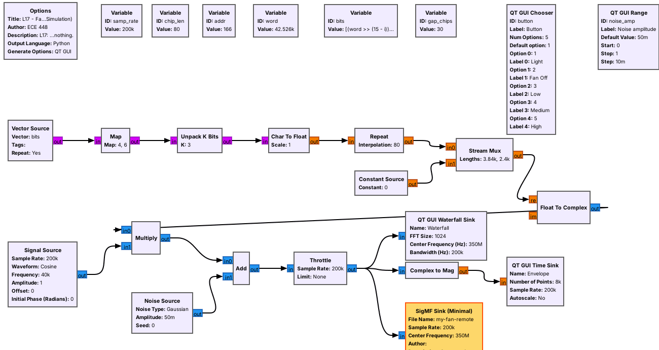 Map 0 to 4 and 1 to 6; Unpack K Bits with K = 3 gives `100` and `110`.
Note:
Repeat holds each chip 80 samples. The Stream Mux takes 3840 samples of frame and 2400 of zeros, the 12 ms gap. L17-encoder.grc is the same chain as a hier block, as in the 2025 class and the wiki's Hier Blocks and Parameters tutorial.
---
## Step 4: Check the Encoder
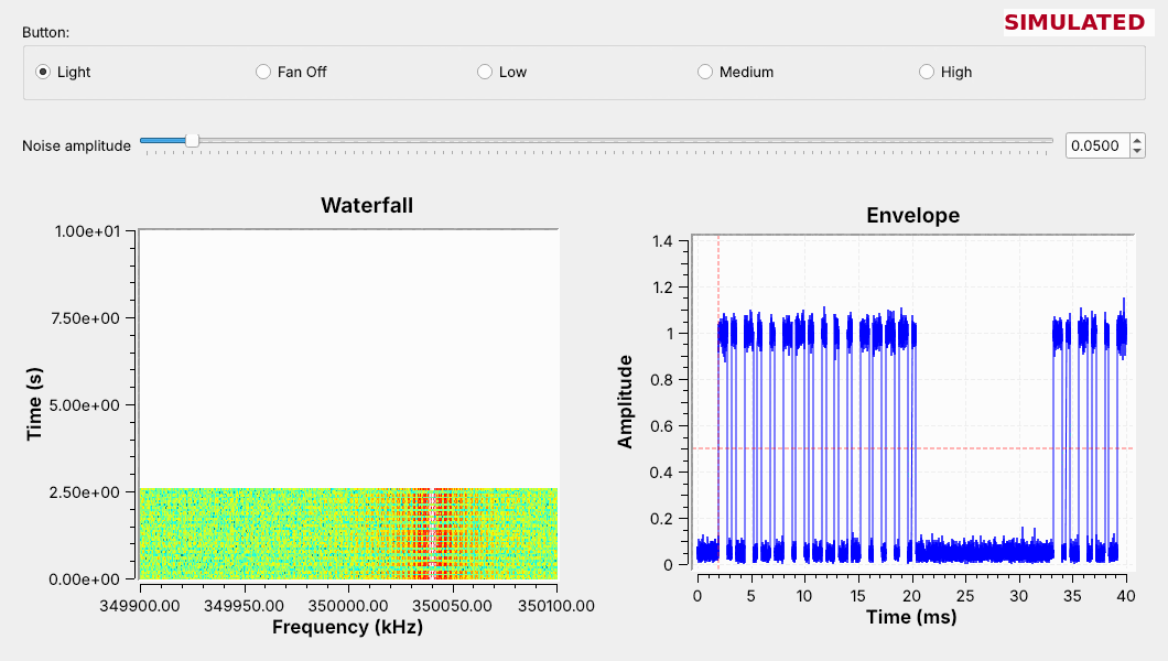 Open `my-fan-remote.sigmf-data` in `L17-chips.grc`: its chips should match the recording.
Note:
Matching chips are the test of steps 1 to 3. The encoder repeats for as long as it runs; the remote stops after six frames.
---
## Step 5: Transmit
- The PlutoSDR sends at 915.04 MHz, not 350 MHz, and 1 MS/s, so `chip_len` is 400.
- Cadets: TX port into a 30 dB attenuator and a second PlutoSDR running `L17-capture.grc`.
- My demo: the classroom's Hunter fan, over the air, at very low power.
Note:
Cadets transmit into a cable with the 30 dB attenuator, or, if I say so, over the air at 915 MHz at low power, with TX attenuation at 30 dB or more, and at 915 MHz, in the 902 to 928 MHz ISM band: a signal the course makes never goes out on the real device's frequency, and the remote's 350 MHz is an FCC Part 15 frequency, not an ISM band. The second Pluto records at fc = 915e6; open the recording in L17-chips.grc at 1 MS/s with a chip length of 400 and raise the envelope gain. Then run the demo: record the classroom fan's remote, decode it with Steps 1 to 3, and send its Light command from your own encoder flowgraph over the air, a few meters from the fan, at the lowest power that still works it. The fan obeys a transmitter it has never seen, because a fixed code cannot tell the two apart. The cadet Pluto flowgraphs are compiled only; the L17 Lab is their first run on hardware.
---
## Key Point