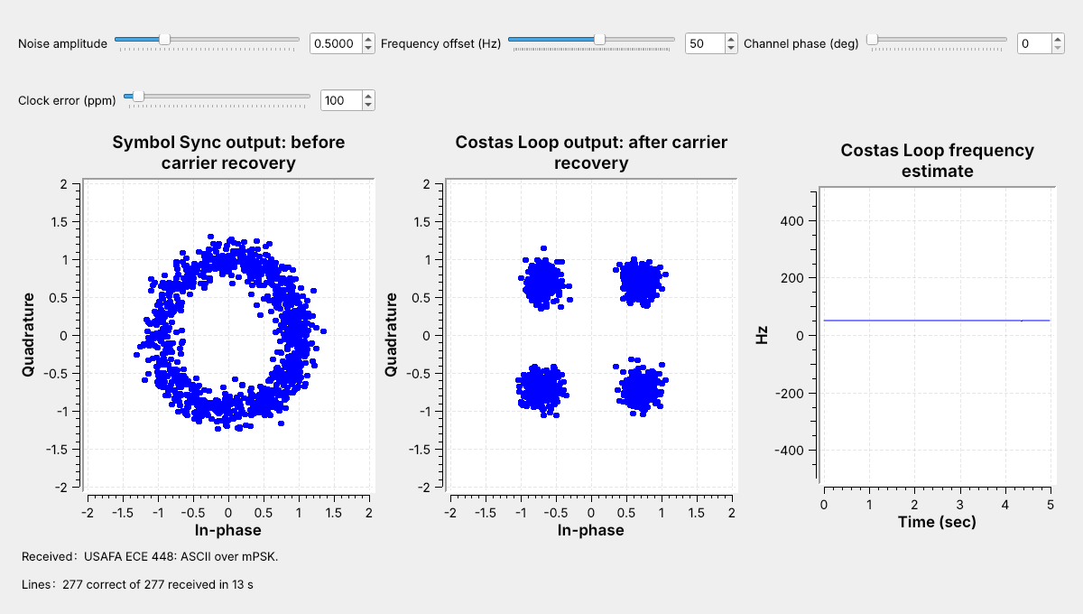
 The points form a ring before the Costas Loop and four clusters after it, and the text arrives.
Note:
Run L15-psk-link.grc live and type 50 into the frequency offset box; the slider opens at 0. The left plot is Symbol Sync's output: the 50 Hz offset turns the constellation 4.5 degrees a symbol, so the points fill a ring. The middle plot is after the Costas Loop.
---
## Phase-Shift Keying
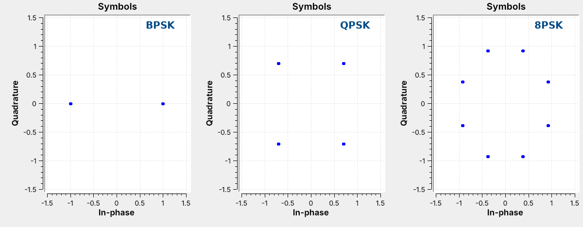 $M$ points on a circle carry $k = \log_2 M$ bits: 1, 2, and 3.
Note:
Switch the chooser in L15-psk-tx.grc. QPSK sits at 45 degrees plus multiples of 90, and 8PSK at 22.5 plus multiples of 45, where the Costas Loop's detectors expect the points.
---
## Step 1: The Transmitter
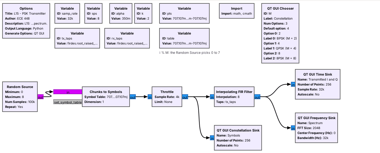 Chunks to Symbols picks each point, and Lesson 9's RRC filter shapes it. Every $M$ fills 5.4 kHz.
Note:
The band is (1 + alpha) times the symbol rate, 1.35 times 4 kHz, whatever M is. More bits per symbol move more data in the same band, but the points sit closer together. Lessons 9 and 10 showed how the roll-off alpha sets the band. GNU Radio's Constellation Modulator packs this chain into one block; L15-psk-multipath.grc uses it.
---
## Step 1: Bits to Points
Repack Bits groups $k$ bits; a **Map** turns them into a phase index.
Note:
The phase index is in amber and the Gray label in blue. Neighbors differ in one bit, so a slip to a neighbor corrupts one bit. The label of index i is i XOR (i shifted right one).
---
## Bits per Symbol
| | $k$ | Bit rate | Point spacing |
| :-- | :-: | :-: | :-: |
| BPSK | 1 | 4 kb/s | 2.00 |
| QPSK | 2 | 8 kb/s | 1.41 |
| 8PSK | 3 | 12 kb/s | 0.77 |
All three run at 4,000 symbols per second in the same 5.4 kHz.
Note:
QPSK doubles BPSK's rate in the same band; 8PSK adds half again. The spacing is for points on a circle of radius 1: more points sit closer together. The link's Noise amplitude slider is the same for every M.
---
## Step 2: The Channel
- Noise spreads each point into a cloud.
- A fixed phase rotates the constellation.
- A frequency offset spins it into a ring.
- A clock error slides the sampling instant.
A 50 Hz offset turns the points $360° \times 50/4000 = 4.5°$ a symbol.
Note:
These are Lesson 3's four problems. Two oscillators are never equal, and the path sets an unknown phase.
---
## The Receiver
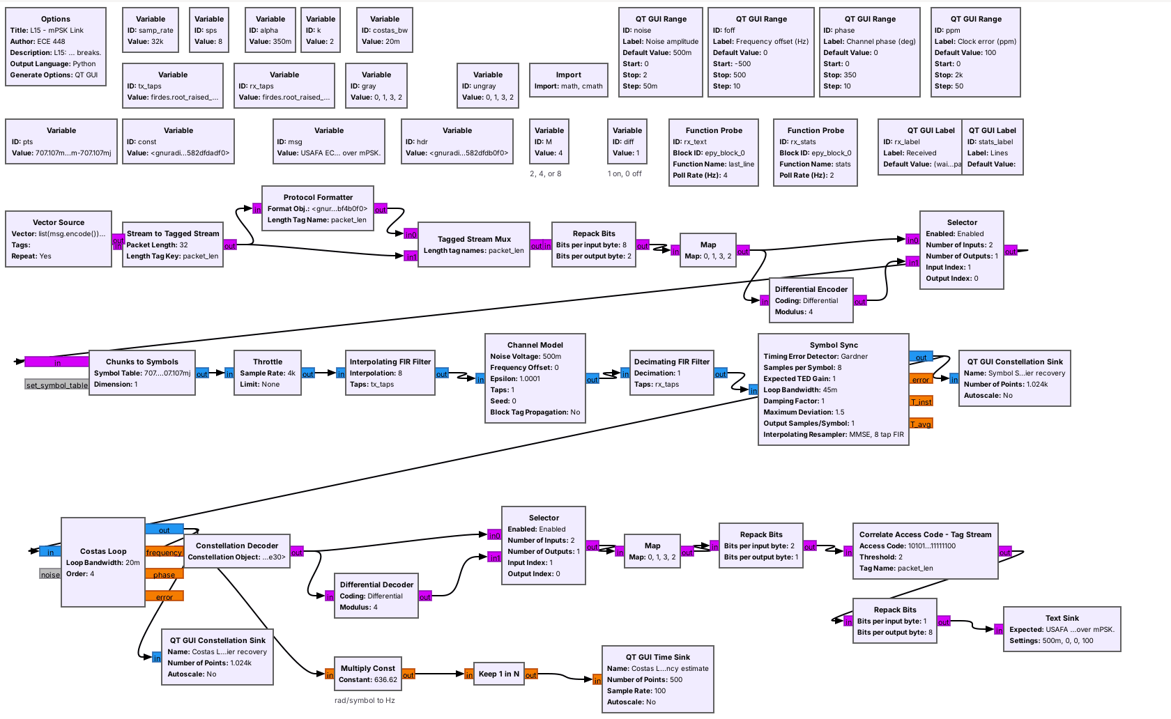 The matched filter and Symbol Sync come first, then the Costas Loop and the Constellation Decoder.
Note:
The Channel Model adds noise, a frequency offset, a fixed phase, and a clock error. Symbol Sync keeps Lesson 9's settings: Gardner, 8 samples per symbol, loop bandwidth 0.045.
---
## Step 3: Timing Recovery
- Symbol Sync locks with the carrier still spinning.
- The Costas Loop then works on one sample per symbol.
Note:
Gardner's detector compares samples half a symbol apart, and a carrier turning a few degrees per symbol barely changes that comparison. A carrier loop placed first would see samples between symbols, which are not on the constellation. The tutorial uses the Polyphase Clock Sync block here; we keep Lesson 9's Symbol Sync, the one departure from the tutorial.
---
## Step 4: Multipath and the Equalizer
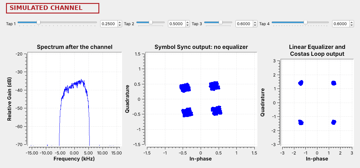 Lowering a tap tilts the spectrum and smears the clusters, and the equalizer pulls them tight.
Note:
Run L15-psk-multipath.grc and lower Tap 2, 3, or 4. The sliders follow Neil's 2025 multipath demo: Tap 3 sets the gain at the band's center, Taps 2 and 4 near its edges, and 1 means flat; Tap 1 sits outside the band. The Linear Equalizer uses CMA, which needs only the fact that every QPSK point has the same amplitude. Very deep dips are beyond it. This is the tutorial's fourth stage.
---
## Step 5: The Costas Loop
The loop rotates each symbol back, measures its error to the nearest point, and updates its phase and frequency.
Note:
For BPSK the detector is I times Q. For QPSK GNU Radio's detector uses the signs of I and Q, and for 8PSK it also checks which of the two is larger, which is why the loop needs the order M. The loop bandwidth here is 0.02: wider locks faster from farther away but lets in more noise.
---
## Acquisition
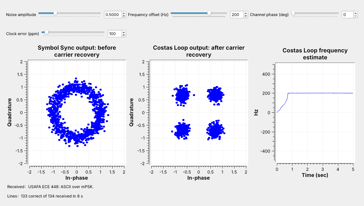 The loop climbs from 0 Hz to the 200 Hz offset in about 0.7 s.
Note:
Type 200 into the frequency offset box. Until the estimate settles the packets fail; after that every line arrives. That time is the acquisition time.
---
## Pull-In Range
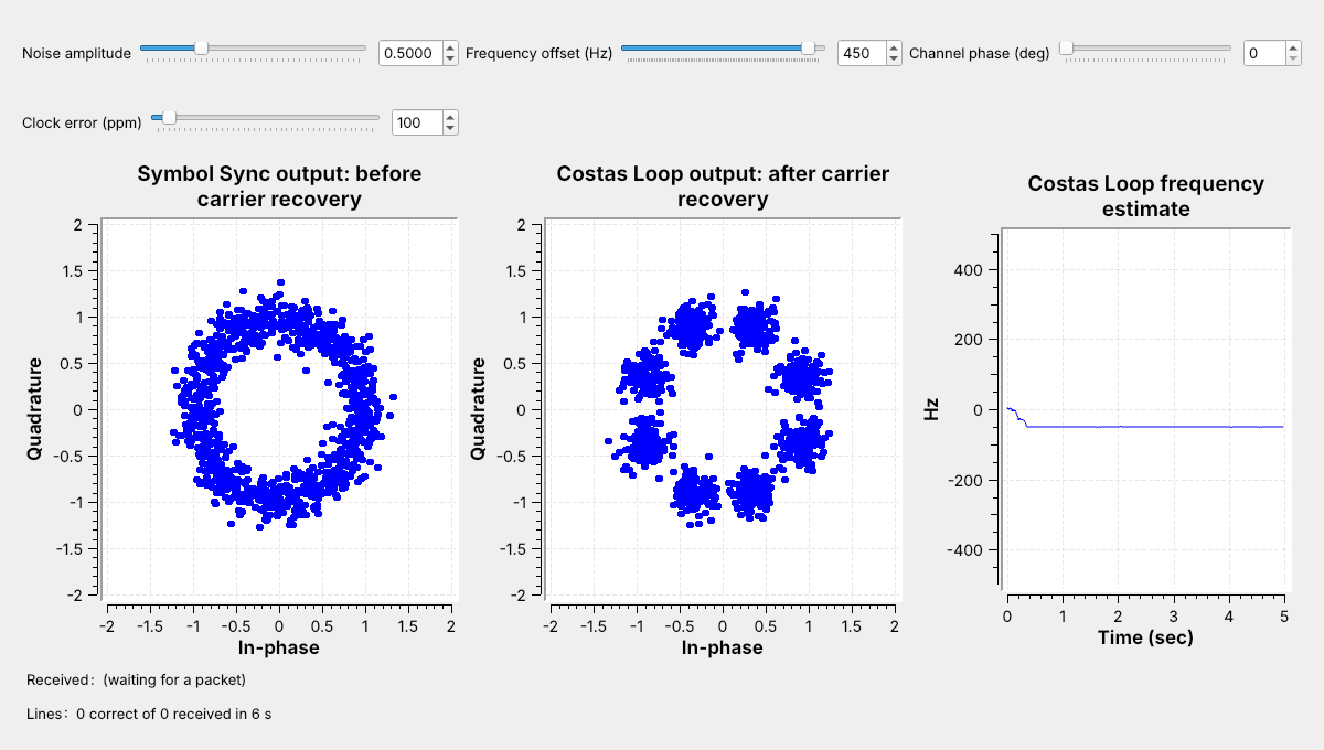 At 450 Hz the QPSK loop settles at −50 Hz, which is a false lock.
Note:
Left 500 Hz off, the points turn 45 degrees a symbol and alternate between eight positions, where the detector's error averages to zero. Real receivers remove most of the offset first, often with an FLL Band-Edge block; two Plutos at 915 MHz can differ by tens of kilohertz, while one Pluto looped back has almost none.
---
## Step 6: Phase Ambiguity
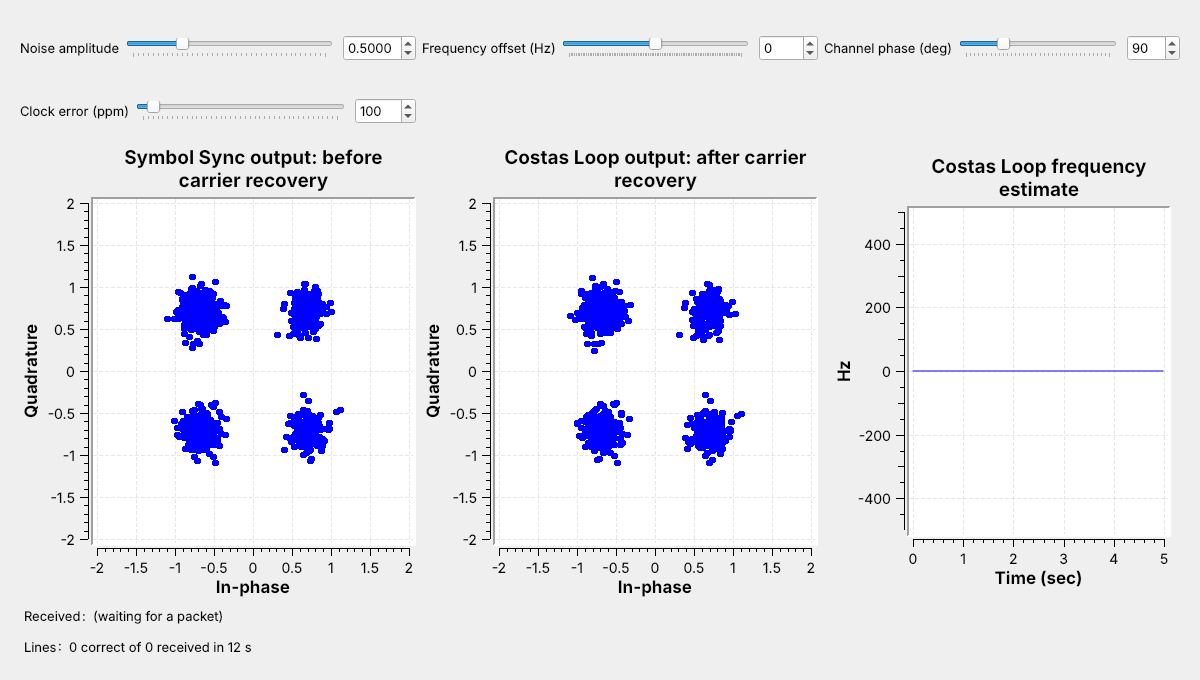 The loop locked one point away. The constellation looks perfect, but no text arrives.
Note:
A QPSK constellation turned 90 degrees looks the same, so the loop can lock in any of M positions. BPSK has 2 lock positions, QPSK 4, and 8PSK 8. This is Lesson 10's polarity switch.
---
## Step 6: Differential Decoding
| Index sent | 0 | 1 | 3 | 3 | 2 |
| :-- | :-: | :-: | :-: | :-: | :-: |
| Received, one step off | 1 | 2 | 0 | 0 | 3 |
| Change, mod 4 | – | 1 | 2 | 0 | 3 |
Send the change in phase; a rotation shifts every index but leaves the differences unchanged.
Note:
The Differential Encoder adds each index to the last one sent, mod M; the decoder subtracts. One wrong decision corrupts two changes, so it corrupts two symbols of data. In the flowgraph the variable diff picks the coded or uncoded path at both ends; change it and run again.
---
## Carrier Recovery Explorer
- Start with QPSK at 100 Hz.
- Raise the offset until the loop stops locking.
↗ Interactive on the lesson page
Note: The explorer runs GNU Radio's Costas Loop algorithm at one sample per symbol for 10 s, with loop bandwidth 0.04, twice the link's. --- ## Noise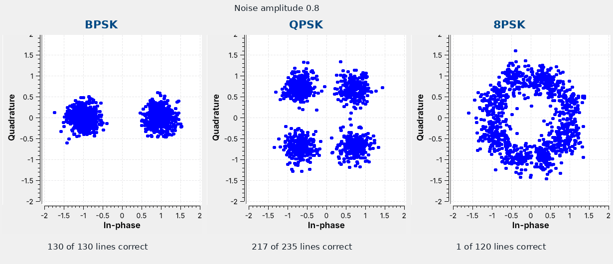 At the same noise, the 8PSK clouds merge first.
Note:
Run the link with noise amplitude 0.8 and change only M. The clouds are the same size each time; the points are not the same distance apart. Raise the noise a step at a time and watch the Received label break up. The lab records where each one stops.
---
## mPSK on a Real Radio
- The L15 Lab sends QPSK through one PlutoSDR, TX port to RX port, with a 30 dB attenuator.
- The Pluto blocks and an AGC replace the Channel Model.
- Nothing in L15 transmits over the air.
Note:
In class we transmit only into a cable, into a shielded enclosure, or at very low power in an ISM band, and only when the lesson says to. Each start brings a new carrier phase. The PlutoSDR flowgraph has run only in simulation so far; the lab is its first run on hardware.
---
## Key Point