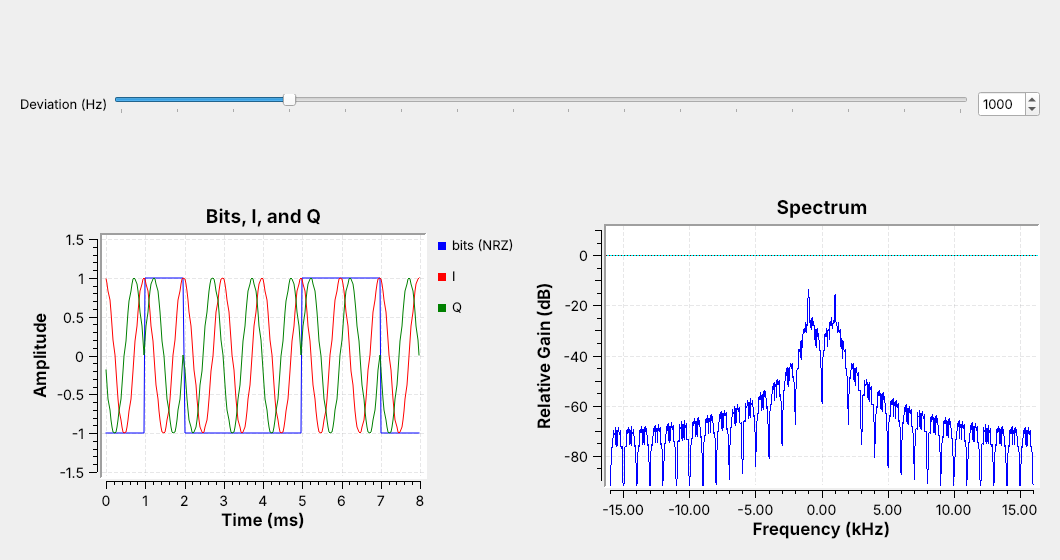
 A 1 is a tone at $+\Delta f$ and a 0 is a tone at $-\Delta f$; here $\Delta f = 1$ kHz.
Note:
Run L08-fsk-tx.grc. Point at the two spectral peaks first, then at the time plot. I is the same 1 kHz cosine during every bit, because a cosine cannot tell which way the phase turns. Q can: it flips relative to I each time the bit changes, the complex-tone idea from Lesson 5.
---
## Where FSK Is Used
- Pagers, weather balloons, and amateur APRS
- Key fobs and garage-door remotes at 315 and 433.92 MHz
- Bluetooth and many drone links, as Gaussian FSK (GFSK)
The envelope is constant, so the power amplifier can run at full output.
Note:
Ask who has a car key fob on them. Lesson 17 records and decodes those. GFSK is FSK with a Gaussian filter on the bits, and the receiver blocks are the same.
---
## The Transmitter
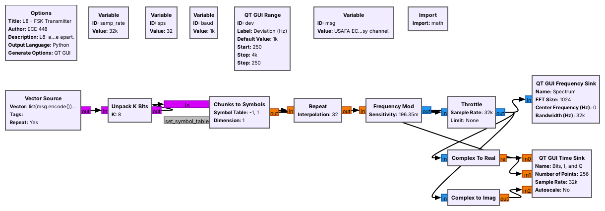 Bytes become bits, bits become $\pm 1$, and **Frequency Mod** turns each $\pm 1$ into a tone.
Note:
Walk the chain left to right. Frequency Mod is the FM transmitter block; the only difference between FM and FSK is that the message is a square wave of bits. The VCO (complex) block, which the 2025 class used, does the same job. The block keeps the phase continuous between bits, which keeps the spectrum compact.
---
## Three Numbers Set the Signal
$$R_s = \frac{f_s}{\text{sps}} = \frac{32\ \text{kHz}}{32} = 1000\ \text{baud}$$
$$k = \frac{2\pi \Delta f}{f_s} = 0.196\ \text{rad/sample}$$
$$h = \frac{2\Delta f}{R_s} = 2$$
Note:
Symbol rate, deviation, and modulation index. k is what Frequency Mod calls its sensitivity; show it in the block's properties. h compares the tone spacing with the symbol rate.
---
## Bandwidth
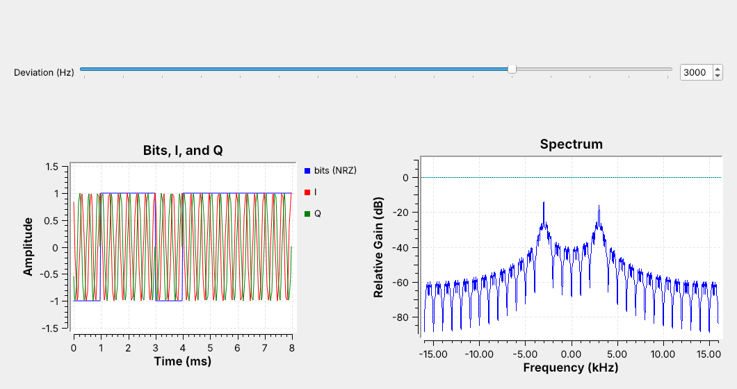 $$B \approx 2(\Delta f + R_s)$$
At 1000 baud, 1 kHz of deviation takes about 4 kHz and 3 kHz takes about 8 kHz. The number sets the receiver's filter.
Note:
Drag the deviation slider live from 1 kHz to 3 kHz and let the class watch the spectrum widen. This is Carson's rule from FM, used only to set the receiver's first filter. Wider deviation separates the tones but a wider filter lets in more noise.
---
## The Channel
- Open `L08-fsk-link.grc`: transmitter, channel, and receiver in one file.
- The **Channel Model** adds noise and a frequency offset, each on a slider.
- Drag the noise slider: the tones stay put, the floor moves.
Note:
The top row is the transmitter they just saw. Run it, drag the noise slider up and down so they see the floor move, then set it to 0.3 and leave the offset at 0 while walking the receiver.
---
## The Receiver
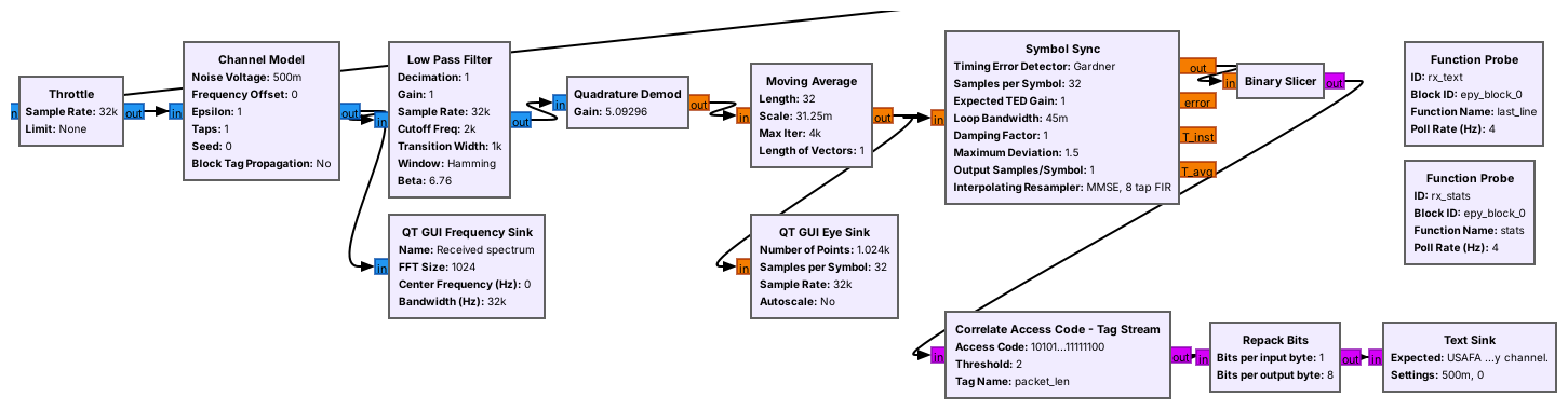 Filter to the signal, turn frequency into a number, and decide each bit.
Note:
The low-pass cutoff is deviation plus symbol rate, 2 kHz: the filter passes minus 2 to plus 2 kHz, the 4 kHz band.
---
## The Quadrature Demodulator
- It measures the phase step from one sample to the next.
- A phase step of $2\pi f/f_s$ is a frequency $f$.
$$g = \frac{f_s}{2\pi\Delta f} = 5.09$$
The tone at $+\Delta f$ comes out as $+1$, and the tone at $-\Delta f$ as $-1$.
Note:
The gain is the reciprocal of the transmitter's sensitivity, so the demodulator undoes the modulator. This is the same block as in an FM receiver.
---
## Save It and Look in Audacity
- Add a **File Sink** (float) on the Quadrature Demod output.
- Run a few seconds, then import in Audacity as raw 32-bit float, 32000 Hz.
- Zoom in: the bits are the square wave.
Note:
Do this live; it is the end of the 2025 FSK agenda. File Sink type float, file demod.f32. Audacity: File, Import, Raw Data, 32-bit float, little-endian, 1 channel. Each bit is a flat step near plus or minus 1, sps samples long, with the noise on it.
---
## Finding the Bits
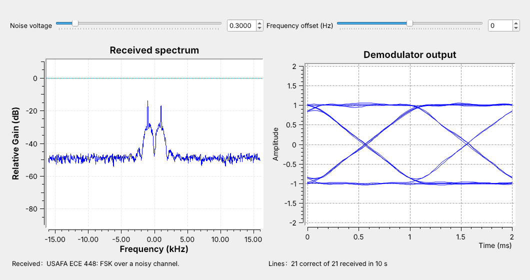 A moving average, **Symbol Sync**, and a **Binary Slicer** at zero decide each bit.
Note:
Explain the eye diagram: many two-bit stretches overlaid. The crossings are bit edges; the gap between them is the eye opening. Symbol Sync samples where the moving average peaks, at the end of each bit, and keeps adjusting its timing because the two clocks never match exactly.
---
## Packets
- The transmitter adds a 64-bit **access code** and a 32-bit header to each line.
- The receiver finds the access code, allowing 2 bit errors, and reads the length.
- Repack Bits rebuilds the bytes; the Text Sink shows the line.
Note:
Without the access code the receiver has bits but no idea where a byte starts. The header holds the line's length in bytes twice, and the receiver passes that many bytes on as bits. Lesson 10 needs the same framing for ASCII over PAM.
---
## Turn Up the Noise
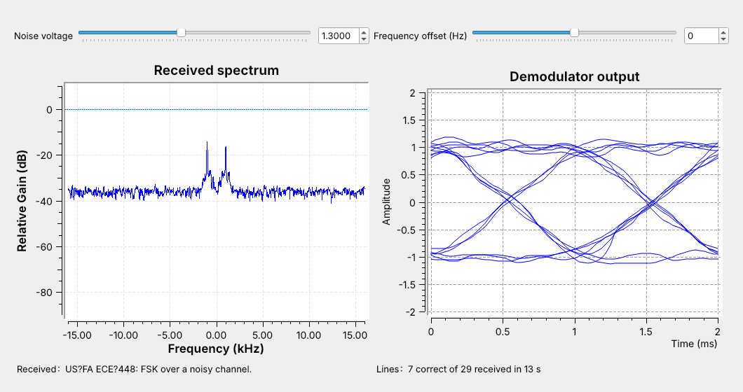 - Low noise: the eye is wide open and every line arrives.
- More noise: the floor climbs, spikes cross zero, and lines have errors.
- More still: almost no packets.
The figure is at 1.3.
Note:
Start from 0.3. Drag the noise slider up slowly and let the class watch the eye thicken, the FM clicks appear, and the line count fall. The fall from clean text to no text takes a small turn of the slider. Tie it back to Lesson 2: a link that only just works fails on the first fade.
---
## FSK Explorer
- Raise the deviation: the tones separate and the band widens
- Raise the noise slowly: note where the first red dot appears
- Double the symbol rate: red dots appear at a lower noise voltage
↗ Interactive on the lesson page
Note: The widget uses the same receiver as the flowgraph but its own link, 48 kHz at 600 to 2400 baud, and an ideal clock, so its numbers are not the flowgraph's or the lab's. --- ## Frequency Offset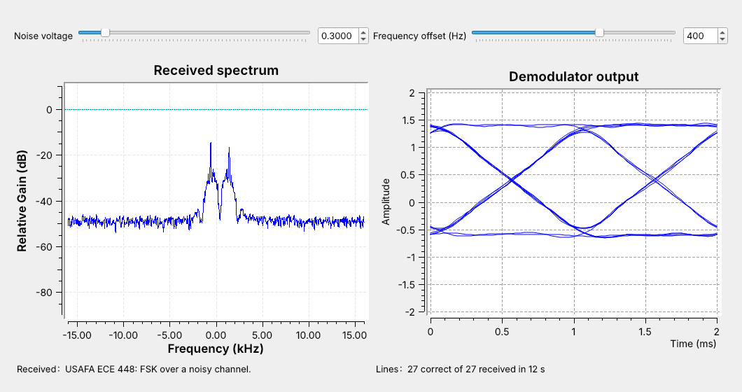 The levels shift by $f_\text{off}/\Delta f$; once the lower level nears zero, the text breaks.
Note:
Demo at noise 0.3 and 400 Hz, then keep dragging until lines start to have errors and then stop. 2 ppm at 915 MHz is 1.8 kHz. Real receivers use a wide deviation or remove the offset before demodulating. The lab measures both.
---
## FSK on a Real Radio
Tone spacing gives $2\Delta f$; the shortest dwell gives $1/R_s$.
Note:
This waterfall is simulated. The tracks are 40 kHz apart, so the deviation is 20 kHz, and the preamble's shortest dwell is 1 ms, so the symbol rate is 1000 baud. On a live waterfall a row often lasts longer than a bit, so measure the dwell on the Quadrature Demod output. To run today's link over the air, replace the Channel Model with a Pluto sink and source. In class we transmit only into a cable through the 30 dB attenuator, and only when the lesson says to. Nothing today transmits.
---
## Key Point