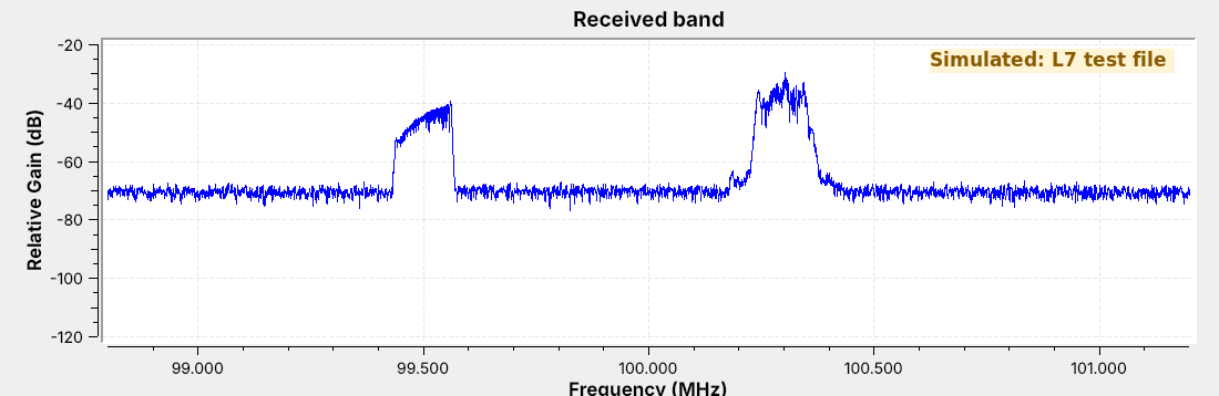
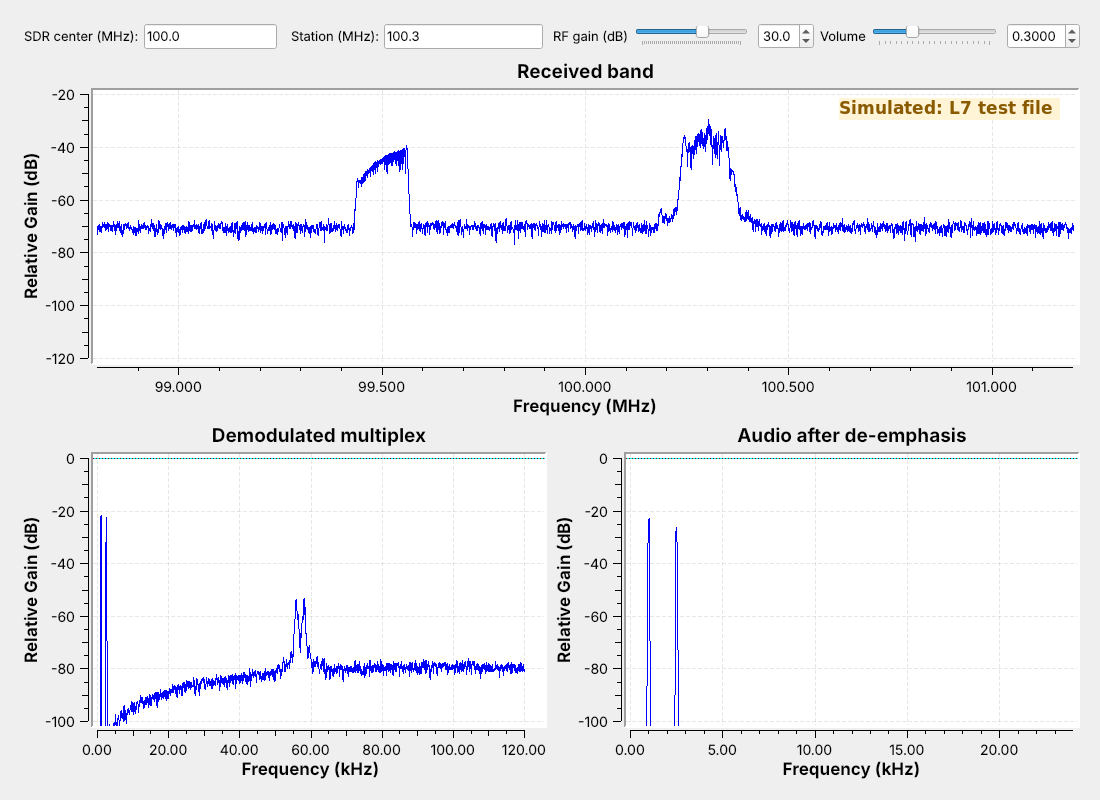
 The goal is audio from the station at 100.3 MHz, and its station name.
Note:
This is a test file from a GNU Radio transmitter flowgraph, the same kind of file as their L5 capture. The station at 100.3 carries the L6 two-tone message and RDS; 99.5 carries a different test tone. The figure carries a Simulated label.
---
## Wideband FM
- The carrier's **frequency** follows the message, up to $\Delta f$ = 75 kHz away.
- A station is about $2(\Delta f + W)$ wide: 180 kHz for 15 kHz audio.
- US stations sit 200 kHz apart.
Note:
The width rule is Carson's rule, a rule of thumb; we use it only to set the channel filter. The 2025 slides' modulation index is beta = deviation / message frequency; broadcast FM at 15 kHz audio has beta = 75/15 = 5. Narrowband FM on two-way radios uses 2.5 or 5 kHz of deviation. AM carrying the same 15 kHz audio would be 30 kHz wide, so broadcast FM is six times wider.
---
## The Receiver Flowgraph
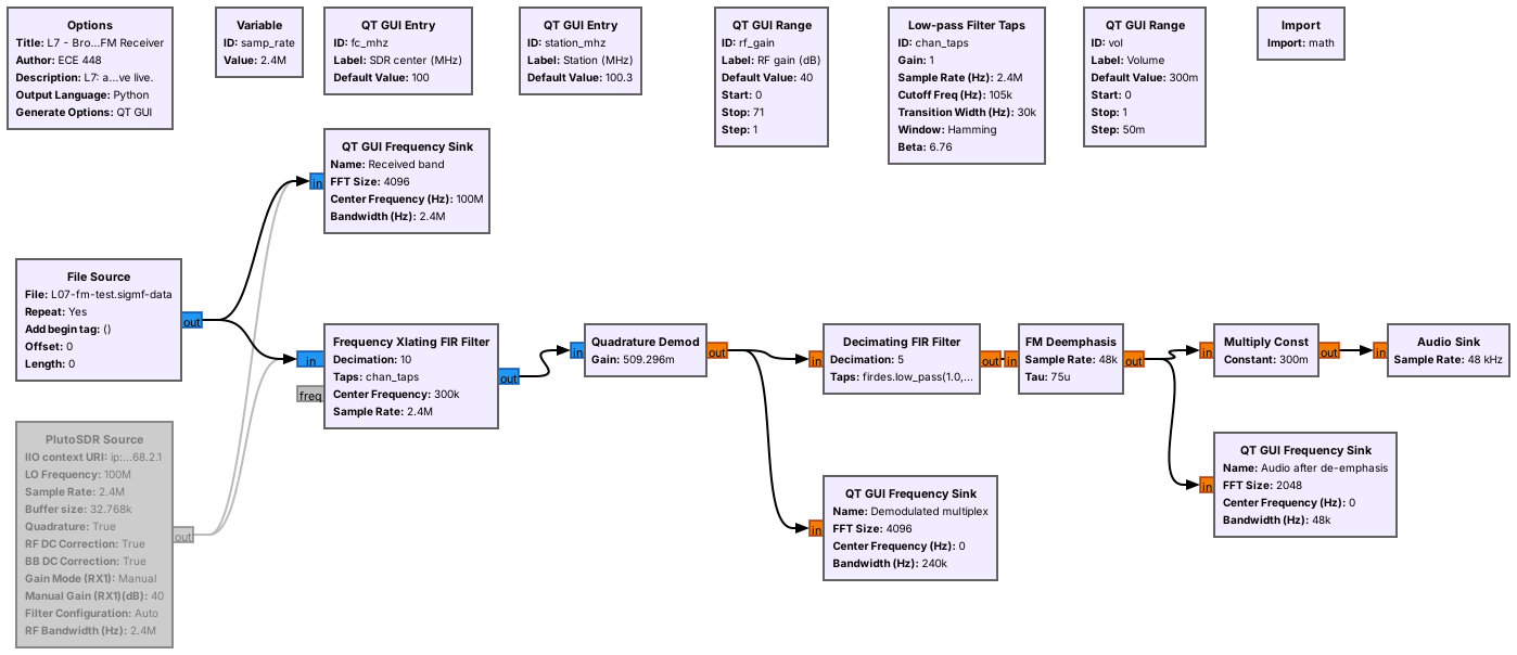 A channel filter, a demodulator, an audio filter, and de-emphasis feed the speaker.
Note:
We disabled the PlutoSDR Source (2.4 MS/s, manual gain); switching to live means disabling the File Source and enabling the SDR. The flowgraph needs no Throttle, because the Audio Sink paces the File Source, as in Lesson 6.
---
## Channel Filter and Decimation
- The **Frequency Xlating FIR Filter** shifts, filters, and decimates in one block.
- It shifts by $f_\text{station} - f_c$ = 300 kHz and passes ±90 kHz.
- Decimating by 10 leaves 240 kS/s.
Note:
The filter has a 105 kHz cutoff and a 30 kHz transition, so it passes 90 kHz and is 28 dB down by 120 kHz, the new Nyquist frequency. The filter removes the station at 99.5. Type 99.5 into Station to tune it instead.
---
## The Quadrature Demodulator
$$\text{gain} = \frac{f_s}{2\pi\Delta f} = \frac{240\ \text{kHz}}{2\pi \cdot 75\ \text{kHz}} = 0.509$$
- The phase step between samples is the frequency.
- With this gain, 75 kHz of deviation gives an output of 1.
Note:
The block ignores amplitude, so an FM receiver needs no AGC.
---
## The Multiplex
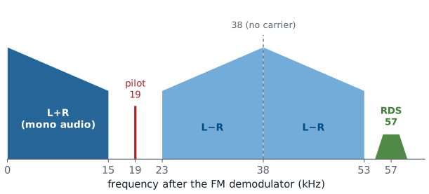 The demodulator's output carries mono audio, the stereo pilot and difference signal, and RDS.
Note:
L-R is DSB-SC on 38 kHz, the Lesson 6 signal that needs carrier recovery; the 19 kHz pilot lets the receiver rebuild 38 kHz by doubling it. RDS sits at 57 kHz, three times the pilot. The test station is mono, so it has no pilot; its RDS stereo flag is only a data bit.
---
## The Multiplex, Measured
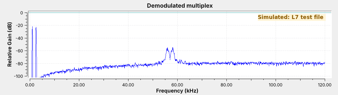 The noise floor rises with frequency.
Note:
FM noise at the demodulator output grows with distance from the carrier, so the top of the audio band and RDS receive the most noise. That rising noise is the reason for de-emphasis, on the next slide.
---
## Audio and De-emphasis
- A 15 kHz low-pass filter decimates by 5, from 240 to 48 kS/s.
- **De-emphasis** (75 μs) cuts the treble the transmitter boosted.
- It removes the high-frequency noise along with the boost.
Note:
The transmitter boosts the treble; the receiver cuts it back, and the noise with it. Europe uses 50 microseconds.
---
## Running the Receiver
 Note:
Play the audio. The audio sink shows exactly the two message tones. Type 99.5 into Station and a different test tone plays. Then show how to point the File Source at fm_capture.cfile and type its center frequency.
---
## RDS
- The **Radio Data System** sends 1187.5 bit/s on 57 kHz.
- It is BPSK: a DSB-SC signal that needs its carrier recovered.
- It carries the station name, program type, and radiotext.
Note:
1187.5 is 57 kHz divided by 48. The bits are differentially coded, so a 180 degree error in the recovered carrier does no harm. The PS name is eight characters, sent two at a time. North America calls it RBDS.
---
## Decoding RDS
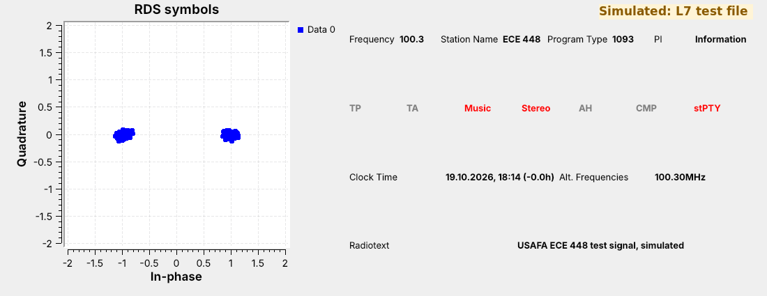 Two clusters show BPSK with its carrier recovered, and the panel shows ECE 448.
Note:
Open L07-rds-rx.grc. It shifts 57 kHz to 0 and resamples to 19 kHz, 16 samples per bit. A matched filter and Symbol Sync find the bit timing, the Constellation Receiver recovers the carrier, and a Differential Decoder feeds the gr-rds blocks. The panel swaps two labels: the PI code, 1093, appears under Program Type.
---
## An AM Receiver
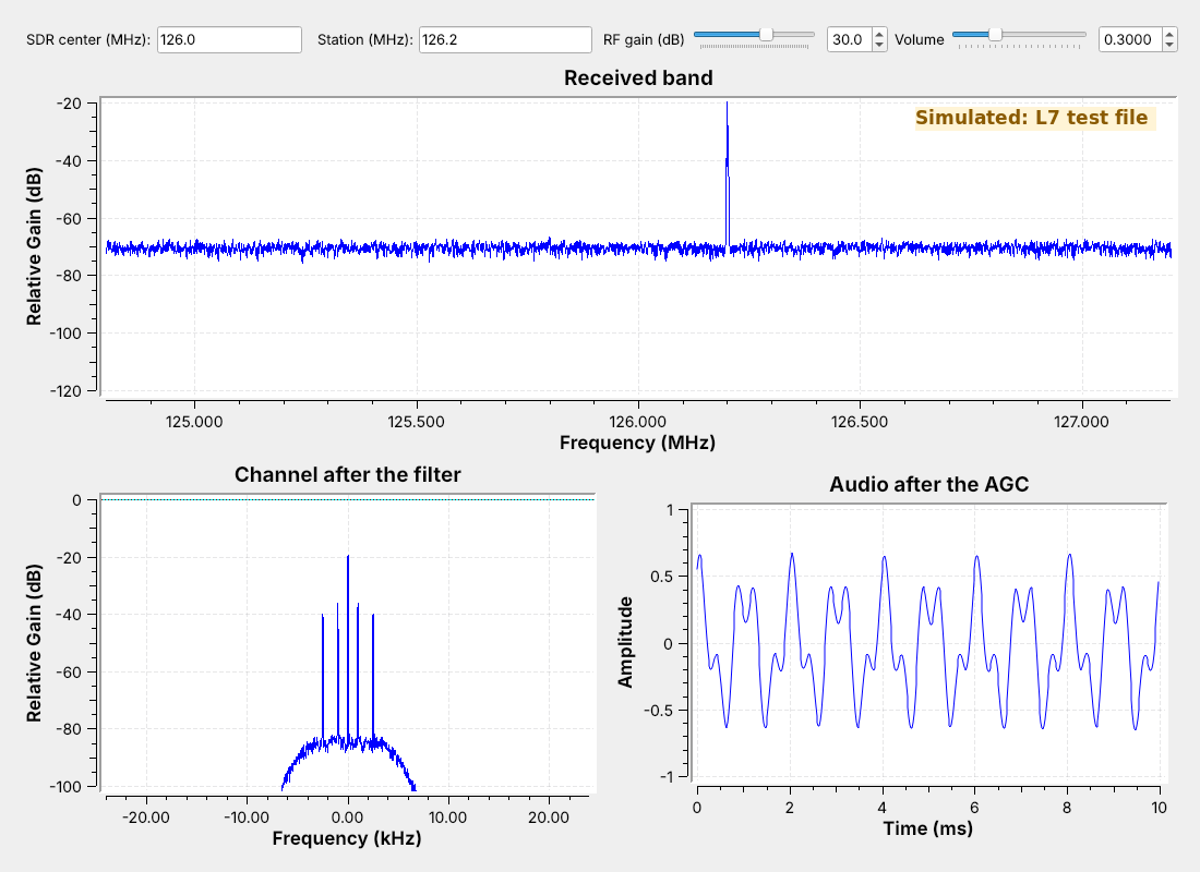 The filter cuts off at 5 kHz and decimates by 50, and **Complex to Mag** detects the envelope.
Note:
Aircraft and ATIS are AM between 118 and 137 MHz. After Complex to Mag it is the L6 receiver: the 3 kHz low-pass taps and a DC Blocker, plus an AGC because the level depends on distance.
---
## AM and FM in the Same Noise
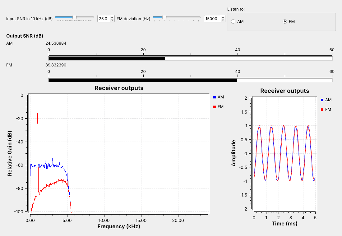 Same tone, power, and noise: with a strong signal, FM's meter reads well above AM's.
Note:
L07-am-vs-fm.grc sends AM at m = 1 and FM with the same transmitted power and the same noise. Demo at 15 kHz deviation and 25 dB Input SNR; the lab uses other settings, so don't read the meters at the lab's. The FM receiver's wider channel lets in more noise, and its output is still the cleaner one; FM's noise floor sits well under AM's. Drag the deviation up and FM's meter climbs; drag it down and most of the advantage goes away.
---
## Turning the Noise Up
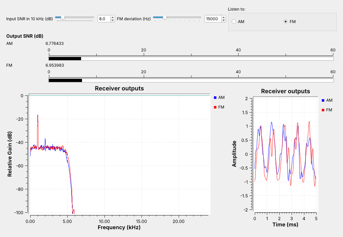 - Far enough down, FM breaks into clicks and its advantage is gone.
- AM only gets steadily noisier.
Note:
At 15 kHz deviation, drag Input SNR down with the speaker on FM and let them hear the clicks start; don't call out the slider value, which the lab asks them to find at other deviations. Repeat at a narrower and a wider deviation: wider deviation sounds cleaner when the signal is strong and breaks up sooner as the noise rises. Near that point the live meters wander by about 1 dB.
---
## FM Explorer
- Raise the deviation: the lines spread wider.
- Raise the tone frequency: the lines move apart.
- Nearly all of the signal stays inside Carson's band.
↗ Interactive on the lesson page
Note: Start from the L7 flowgraph preset. The point is that the rule of thumb is good enough to set a channel filter. --- ## Key Point