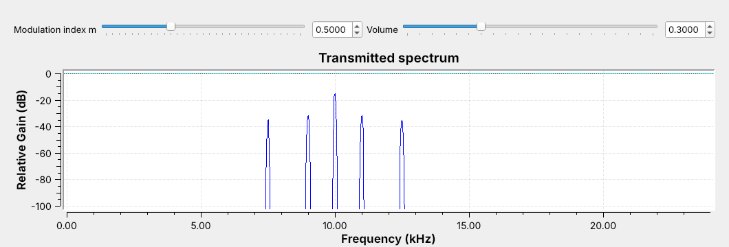
 Modulation moves an audio message up to a carrier, so each transmitter gets its own channel.
Note:
Run the DSB-AM flowgraph and let them hear the two tones. Ask what the five lines are before explaining them.
---
## DSB-AM
$$s(t) = A_c\left[1 + mx(t)\right]\cos(2\pi f_c t)$$
- $m$ is the **modulation index**; the bracket is the **envelope**.
- A tone at $f$ makes sidebands at $f_c - f$ and $f_c + f$.
- The bandwidth is $2W$, here 5 kHz (7.5 to 12.5 kHz).
Note:
Drag m on the frequency sink: the sideband lines grow and the carrier stays put. The louder 1 kHz tone makes the taller pair.
---
## The DSB-AM Flowgraph
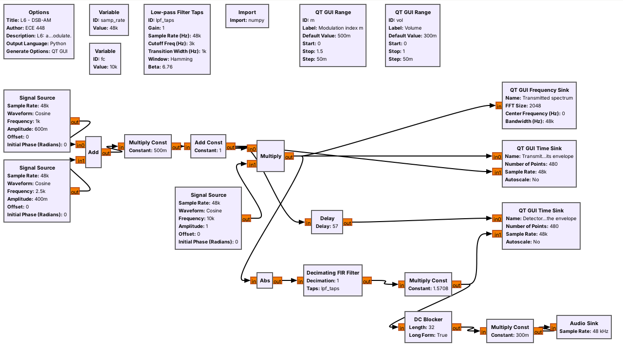 The Audio Sink paces the flowgraph, so there is no Throttle.
Note:
Walk the top row against the equation: add, Multiply Const m, Add Const 1, Multiply by the carrier. The sound card takes exactly 48,000 samples per second, which is the hardware clock from Lesson 5.
---
## Modulation Index
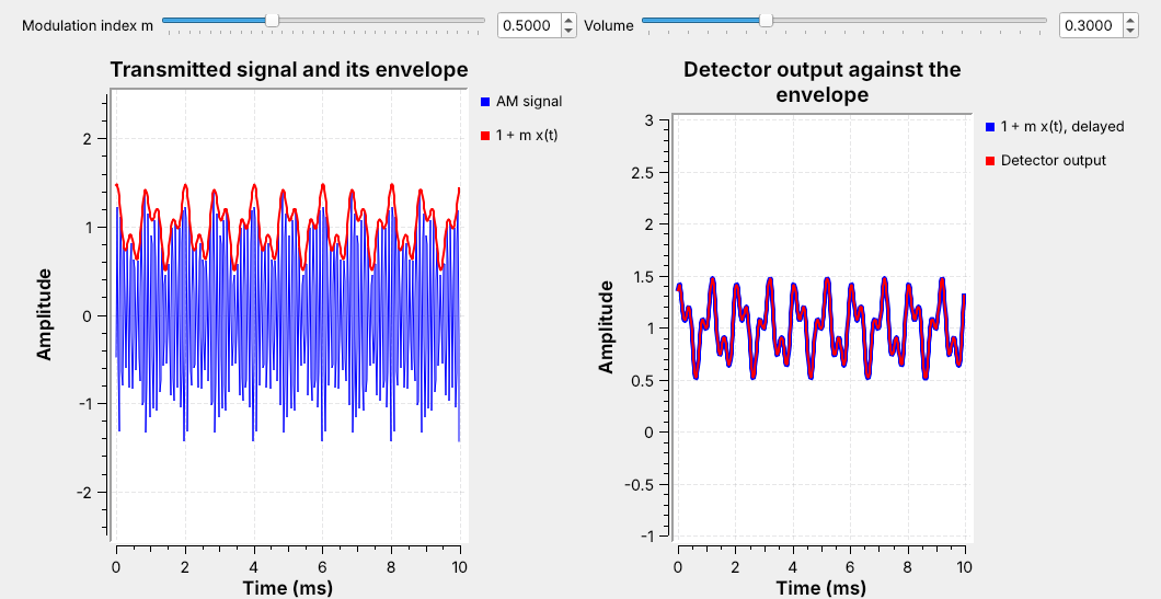 The detector output lies on the envelope: the received audio matches the source.
Note:
The Delay block holds the reference back 57 samples, half the low-pass filter's length, so the two traces line up.
---
## The Envelope Detector
- **Abs** rectifies, like a diode.
- A **low-pass filter** at 3 kHz keeps the envelope and removes the carrier.
- Multiply by $\pi/2$, because a rectified cosine averages $2/\pi$ of its peak.
Note:
This is the crystal-radio receiver in three blocks. The low-pass filter removes everything above the message. The DC Blocker removes the constant 1 before the speaker.
---
## Low-pass Filter Taps
- **Cutoff** 3 kHz and **transition** 1 kHz define the filter.
- GNU Radio picks the length: 115 taps.
- The output lags by half the taps: 57 samples, or 1.2 ms.
Note:
Open the Low-pass Filter Taps block and show the four settings. The 2.5 kHz tone sits just inside the passband. The Delay block's expression, len(lpf_taps)//2, follows the filter if they change it.
---
## Overmodulation
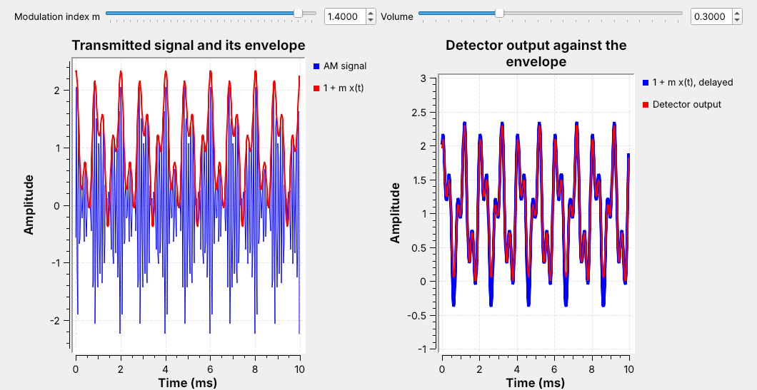 Push $m$ too far and the envelope goes negative; the detector folds it up.
Note:
Drag m slowly from 0.5 to 1.4 with the audio on and ask the class to call out when the traces split and when they hear it. m at or below 1 is safe for any message; this one never quite reaches minus 1, so it holds a little past 1. Overmodulation also spreads the spectrum into the neighboring channel.
---
## DSB-SC
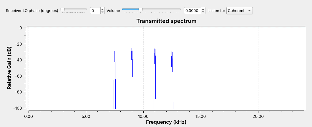 $$s(t) = A_cx(t)\cos(2\pi f_c t)$$
Note:
Open L06-dsb-sc.grc. Same sidebands, same 5 kHz, and no carrier line. All of the power is in the sidebands. Go back to the DSB-AM sink for a moment: its tallest line was the carrier, which carries no information; AM keeps it only so the receiver can be a simple envelope detector.
---
## Coherent Demodulation
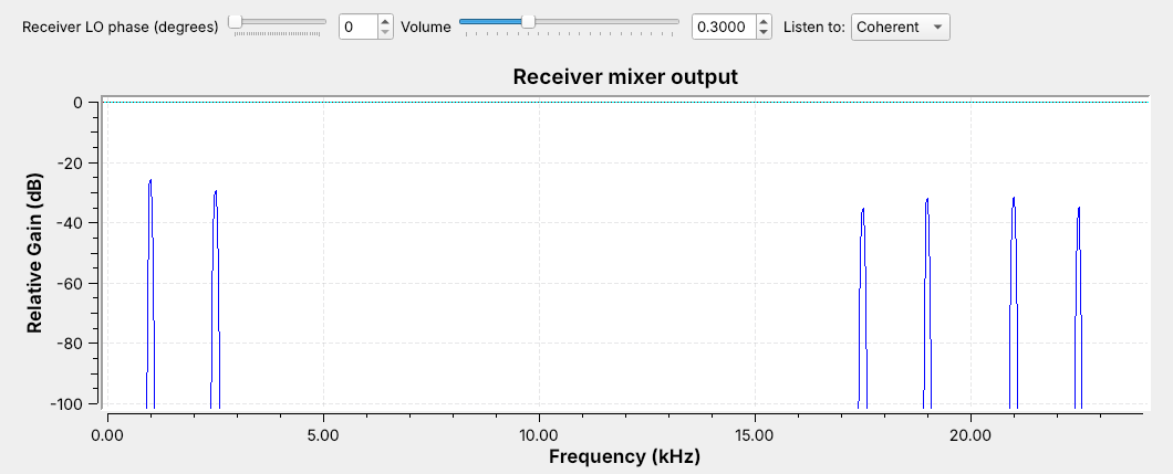 The mixer puts the message back near 0 Hz, with a copy near 20 kHz; the low-pass filter keeps the message.
Note:
This frequency sink sits on the receiver's Multiply output. A Multiply Const of 2 after the filter restores the level, because the mixing leaves half the amplitude near 0 Hz.
---
## Coherent Against Envelope
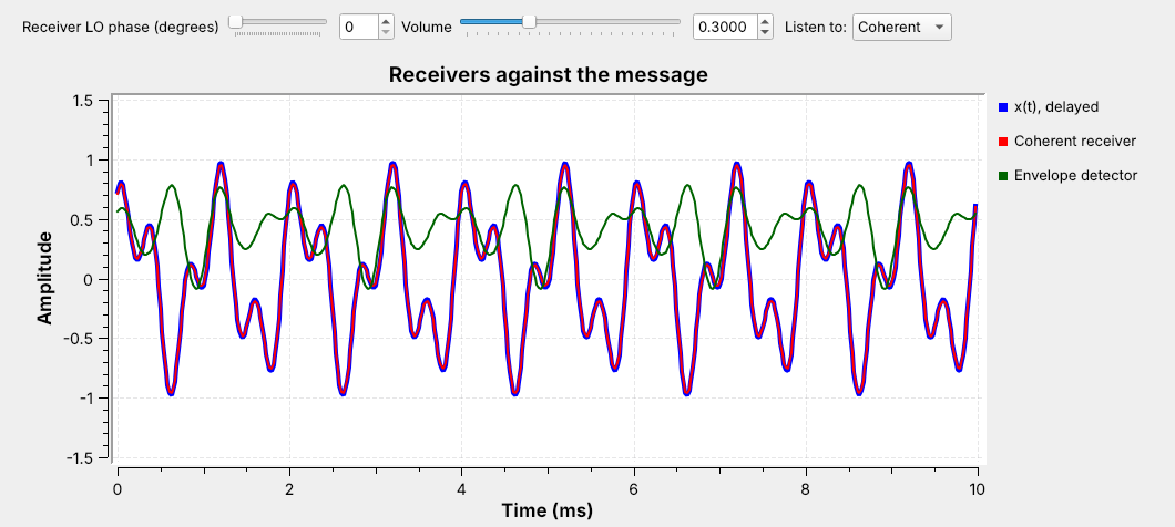 The coherent output (red) lies on the message; the envelope detector (green) gives a filtered $\vert x(t)\vert$.
Note:
Switch Listen To between Coherent and Envelope. The envelope detector recovers the absolute value of the message, which is the same folding as overmodulation.
---
## The LO Must Match
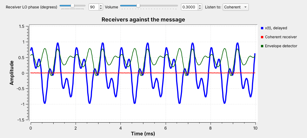 A phase error makes the output smaller; at $90°$ it is zero.
Note:
Drag the LO phase from 0 to 90 with the audio on and let the tones fade out. FM stereo sends a 19 kHz pilot so the receiver can rebuild its 38 kHz LO; that is Lesson 7.
---
## SSB
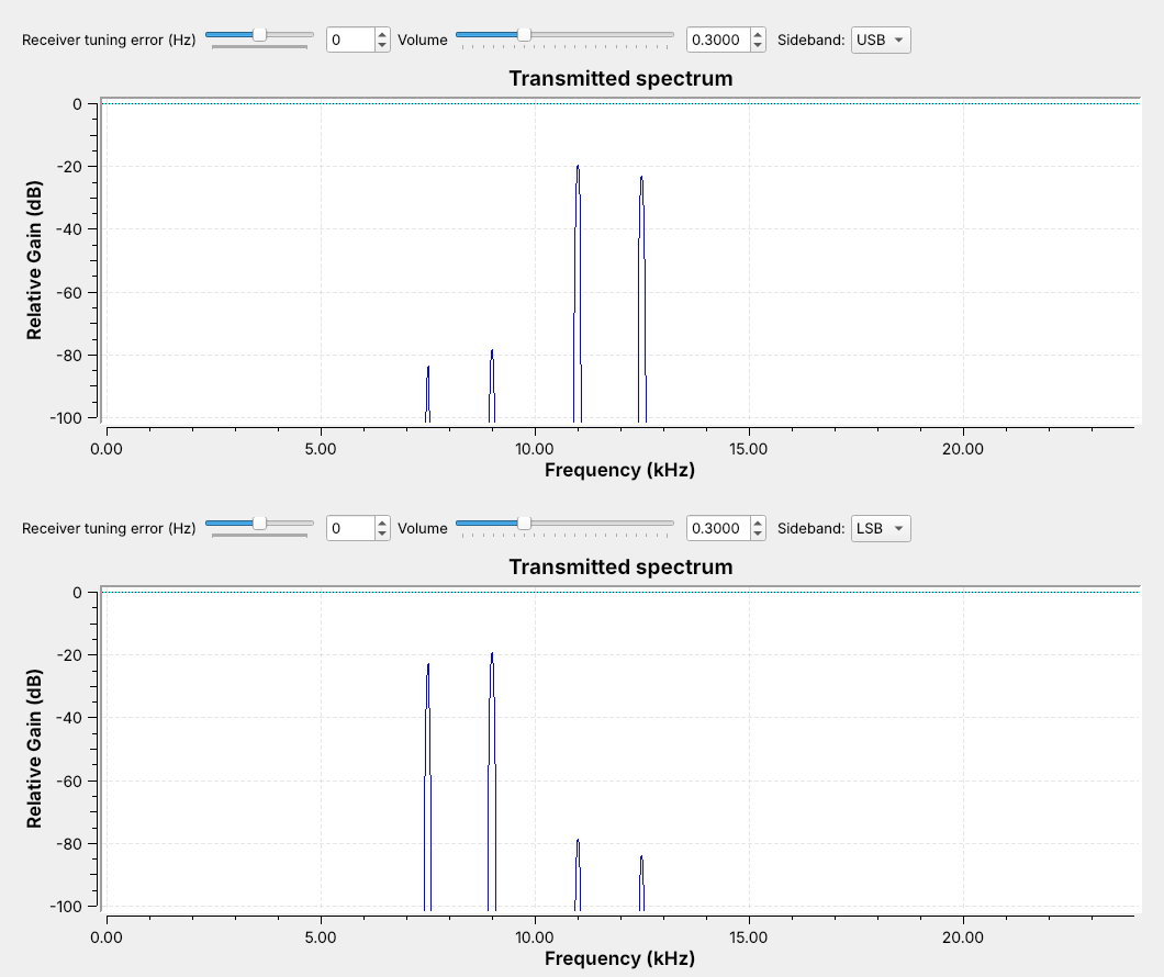 One sideband carries the whole message, in half the bandwidth.
Note:
Open L06-ssb.grc and switch the Sideband menu. Point out that the LSB reverses the spectrum: the higher tone is the line farther below the carrier. The suppressed sideband sits far below the kept lines.
---
## The Phasing Method
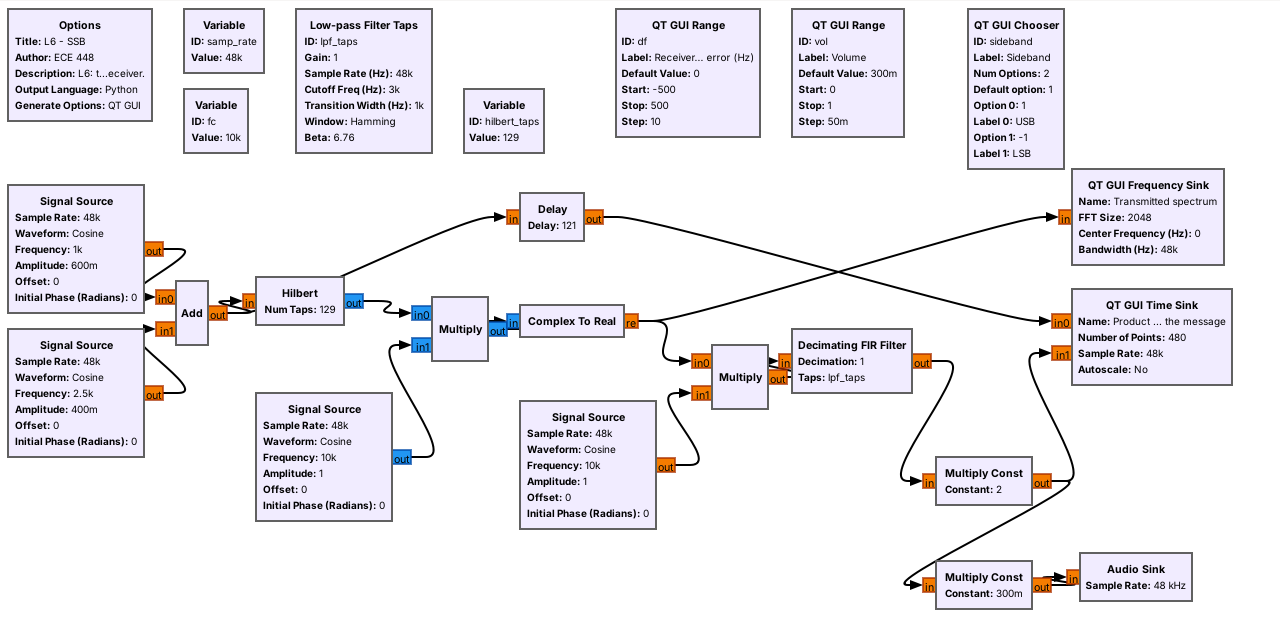 $$s(t) = \mathrm{Re}\left\{z(t)e^{\pm j2\pi f_c t}\right\}$$
Note:
The Hilbert block outputs z(t), the message with only its positive frequencies, the one-direction idea from Lesson 5's complex tone. The sign of the carrier frequency picks USB or LSB.
---
## Receiving SSB
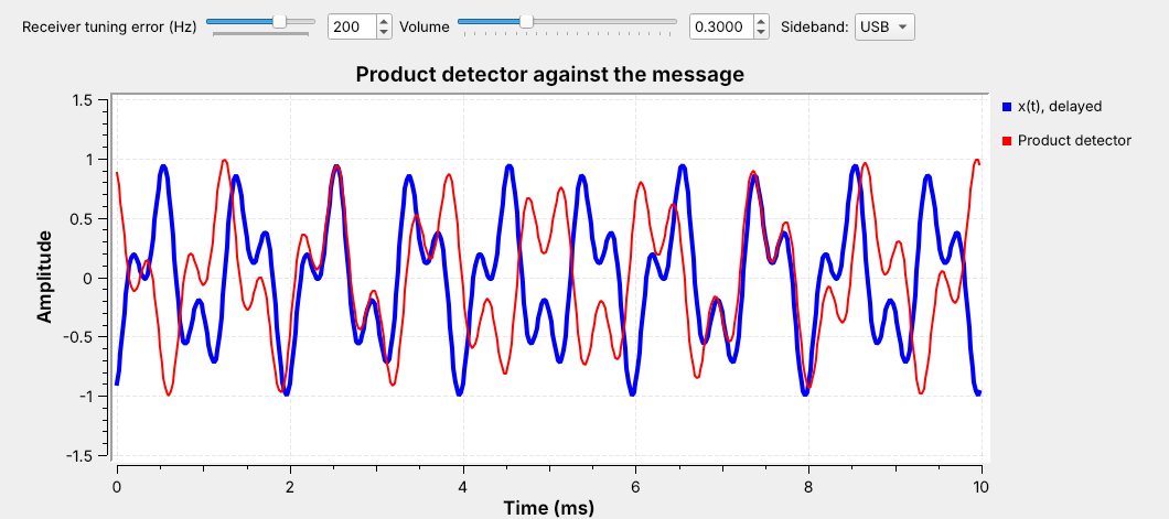 A tuning error $\Delta f$ shifts every audio tone by $\Delta f$.
Note:
Drag the tuning error to plus and minus 200 Hz with the audio on. On USB with the LO 200 Hz high, 1 and 2.5 kHz drop to 800 Hz and 2.3 kHz; on LSB they rise to 1.2 and 2.7 kHz. The tones change pitch but never fade. Speech stays intelligible to about 100 Hz. That is why an SSB operator tunes by ear and needs no carrier recovery.
---
## AM Explorer
- DSB-AM: raise $m$ past 1 and watch the envelope fold
- DSB-SC: the carrier line disappears
- USB and LSB: half the bandwidth, and the envelope is not the message
↗ Interactive on the lesson page
Note: The two-tone SSB envelope is the reason SSB needs a product detector. With one tone the SSB envelope is constant. --- ## Identifying Each on a Spectrum | Signal | Carrier line | Sidebands | Bandwidth | Receiver | | :-- | :-: | :-: | :-: | :-- | | DSB-AM | yes | two | $2W$ | envelope | | DSB-SC | no | two | $2W$ | coherent | | SSB | no | one | $W$ | product | Note: Two questions identify any of them: is there a steady line at the center, and is the signal symmetric about it? --- ## Key Point