# ECE 448
Software Defined Radios
## Lesson 4 — SDR Introduction
Spring 2027 · Dr. Neil Rogers

---
## Where We Were
- Lesson 2: the first amplifier sets the receiver's noise figure
- Lesson 3: a digital signal is points in the I-Q plane
- Today: the hardware that turns a band of spectrum into those points
Note:
Bring a PlutoSDR to the front of the room and pass it around while the next slides are up; every cadet is issued one.
---
## Today's Plan
1. What makes a radio software defined
2. The course SDR: the PlutoSDR
3. Inside an SDR: front end, mixer and LO, I and Q, ADCs
4. Superheterodyne, zero-IF, and direct sampling
5. Sample rate and bandwidth
6. Bits and clipping, in a flowgraph
7. Choosing the radio and its settings
8. Explore a band on the PlutoSDR, in GNU Radio
Note:
Item six runs live from L04-adc-bits.grc, which needs no hardware. If GNU Radio is not yet installed on the projector laptop, use the screenshots on the lesson page. Item eight runs L05-fm-spectrum.grc on a PlutoSDR from the projector laptop.
---
## One Radio, Many Signals
- One PlutoSDR covers every dashed signal; only the software changes.
- An SDR digitizes early and does the rest in software.
- A new job means a new flowgraph, not new hardware.
Note:
The PlutoSDR receives FM at 100 MHz, AIS at 162 MHz, key fobs at 433.92 MHz, ADS-B at 1090 MHz, and Wi-Fi at 2.4 GHz with the same hardware. The course Plutos run in extended-frequency mode, 70 MHz to 6 GHz (325 MHz to 3.8 GHz as shipped). An SDR still needs an antenna, a filter, an amplifier, and a converter; everything after the converter is a program.
---
## The Course SDR: the PlutoSDR
| Specification | PlutoSDR |
| :-- | :-- |
| Tunes | 70–6000 MHz (325–3800 as shipped) |
| Streams over USB | about 4 MS/s |
| Bursts | up to 61.44 MS/s |
| Bits | 12 |
| Transmit | full duplex |
- The PlutoSDR's converters reach 61.44 MS/s, but its USB 2.0 link streams about 4 MS/s without drops.
- Every number comes from Analog Devices' data, linked on the lesson page.
Note:
The PlutoSDR is every lab's radio. Its 70 MHz to 6 GHz is extended-frequency (AD9364) mode, which the course Plutos are set to; live flowgraphs stay at 2 to 4 MS/s and wider signals are captured in bursts. An RTL-SDR a cadet already owns also works as a receive-only extra; no lesson needs it.
---
## Inside an SDR
- Front end: filter and LNA
- Mixer and LO: down to 0 Hz
- ADCs: \(I\) and \(Q\) to the host
Note:
The LNA comes right after the filter because, from Lesson 2, the first amplifier sets most of the noise figure. A transmitter runs the same chain backward with DACs.
---
## The Mixer Moves the Band
\[\cos a \cos b = \tfrac{1}{2}\cos(a - b) + \tfrac{1}{2}\cos(a + b)\]
A low-pass filter keeps the difference; one real mixer also folds the station below the LO onto the positive axis.
Note:
A station at 100.3 MHz with an LO at 100.0 MHz comes out at 0.3 MHz, and the filter removes the 200.3 MHz sum. Setting the center frequency in GNU Radio sets the LO. Point to the amber station: 98.6 MHz lands at 1.4 MHz, on top of 101.4 MHz. I and Q separate them.
---
## I and Q
- One mixer folds \(f_{LO} + \Delta\) and \(f_{LO} - \Delta\) onto the same \(\Delta\).
- A second mixer, with the LO shifted 90°, tells them apart.
- Each sample is \(I + jQ\): it rotates one way above the LO and the other way below, so 98.6 MHz lands at \(-1.4\) MHz.
Note:
Lesson 5 shows the negative frequencies this makes possible on GNU Radio's plots. Do not derive it here.
---
## Superheterodyne
Note:
A classic FM radio: wanted 100.3 MHz, LO1 at 111.0 MHz, IF 10.7 MHz, so the image is 121.7 MHz. Step through: the preselector knocks the image down; the LNA raises signal and noise together (first amplifier sets the noise figure, Lesson 2); the mixer moves everything by 111.0 MHz and adds sum products; the IF filter keeps one channel; the I/Q mixer brings it to 0 Hz. Then check Preselector off and stop at the IF filter: the image sits on the wanted station, and nothing after the mixer can remove it. Transmit runs it backward; the band-pass removes the 121.7 MHz product and the LO leakage before the PA. Course transmitters use 915 MHz.
---
## Three Receiver Architectures
- **Superheterodyne**: two mixers; image rejection and more parts
- **Zero-IF** (the PlutoSDR): one I/Q mixer; a DC spike and I/Q imbalance
- **Direct sampling**: no mixer; a very fast ADC and strong anti-alias filtering
Note:
The ADC moves closer to the antenna in each row. Zero-IF puts anything that leaks into the mixer output at 0 Hz in the middle of the band, one source of Lesson 5's DC spike; mismatched I and Q paths leave a faint mirror of each signal. Direct sampling digitizes the RF band itself, so everything above half the sample rate must be filtered out first or it aliases in. GNU Radio receives complex samples whatever the architecture.
---
## Sample Rate and Bandwidth
- Complex samples at \(f_s\) show a band \(f_s\) wide, centered on \(f_{LO}\).
- GNU Radio carries each sample in 8 bytes: \(8 f_s\) bytes per second.
- 2.4 MS/s is 19.2 MB/s; 20 MS/s is 160 MB/s.
Choose a little more than the signal's bandwidth, not the radio's maximum.
Note:
A laptop that cannot keep up drops samples, and most drivers print an overflow message in the console. The radio's own filters roll off near the window's edges. The next slide cues the SDR Window widget on the lesson page.
---
## SDR Window
- FM on the PlutoSDR at 2.4 MS/s: three stations in view
- Streaming stops at 4 MS/s: a slice of one Wi-Fi channel
- A burst at 20 MS/s: a whole Wi-Fi channel, 160 MB/s
↗ Interactive on the lesson page
Note:
Start on FM with the PlutoSDR and raise the rate past 4 MS/s, where the readout turns to burst only. On the ISM band, show how little of one Wi-Fi channel 4 MS/s covers, then raise the rate to about 20 MS/s to put the whole channel in view, which the Pluto delivers only as a short burst capture.
---
## Bits and Clipping
- An \(N\)-bit ADC has \(2^N\) levels between \(-\)full scale and \(+\)full scale.
- More bits put the converter's own noise floor lower.
- 0 dBFS is full scale; above it, the ADC clips.
Note:
8 bits is 256 levels, 12 bits is 4096. The rounding error acts like a small noise; finer steps mean less of it. Do not derive a dB-per-bit rule; the flowgraph shows it.
---
## The Quantizer Flowgraph
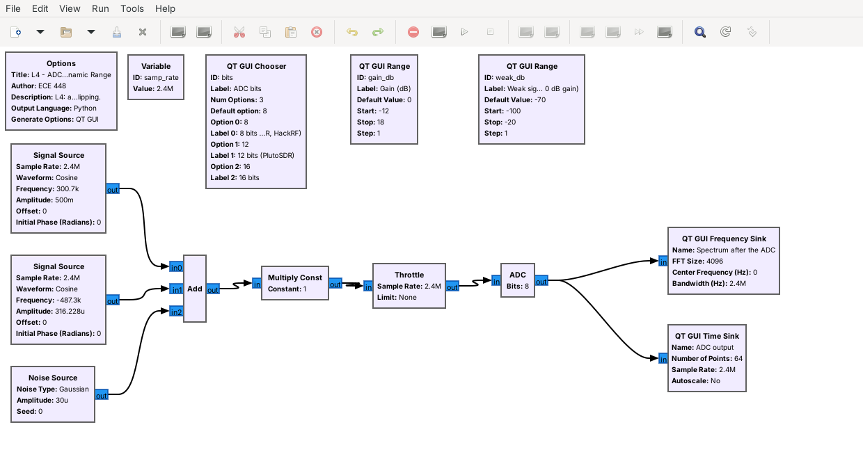 - A strong tone at \(-6\) dBFS and a weak one 64 dB below it
- Then a gain and an ADC block with 8, 12, or 16 bits
Note:
The ADC block is an Embedded Python Block: it clips I and Q to plus and minus one and rounds to 2 to the N levels. The sink's 0 dB is not full scale, so read differences.
---
## 8 Bits
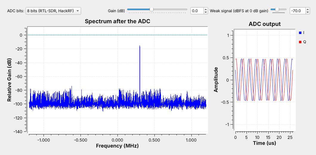 The floor and spurs reach within about 60 dB of the strong tone; the weak tone lies below them.
Note:
Point to minus 0.49 MHz, where the weak tone should be. It sits below the spurs. Because the input is a pure tone, much of the rounding error shows up as spurs rather than smooth noise.
---
## 12 Bits
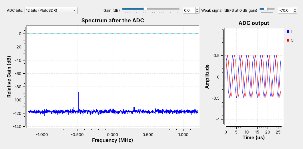 The floor drops about 20 dB and the spurs are gone; the weak tone sits about 40 dB above the floor.
Note:
Switch the menu live. The weak signal did not get stronger; the floor dropped beneath it. Then drag the weak-signal slider down until the tone disappears.
---
## Too Much Gain
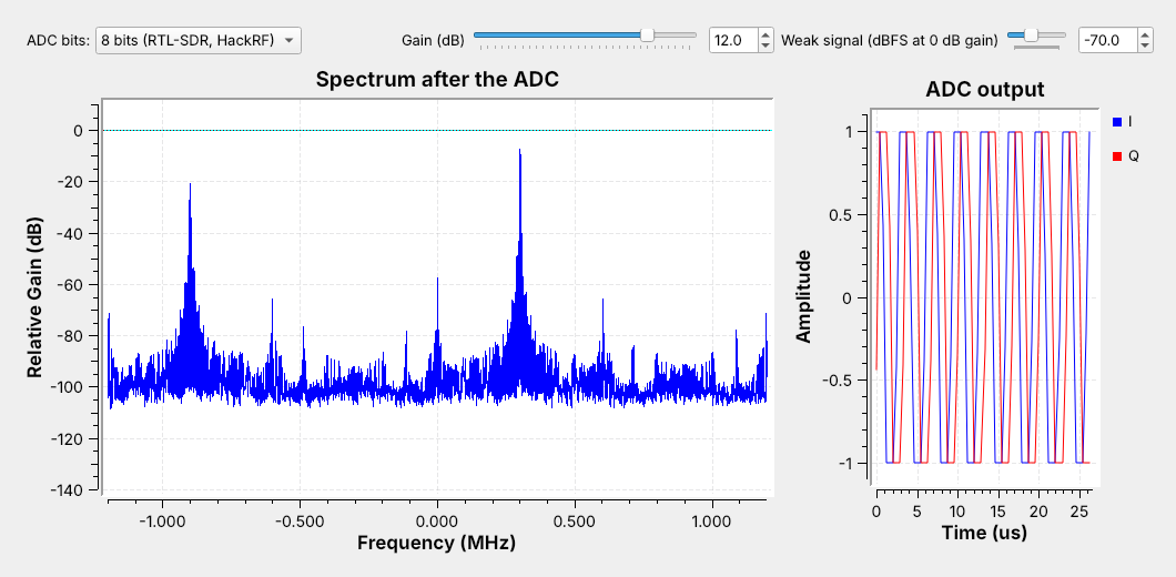 The strong tone rises only 7 dB, and clipping creates a false signal near \(-0.9\) MHz.
Note:
On a real SDR these false signals look exactly like transmissions. Set the gain against the strongest signal in the window.
---
## Choosing the Radio and Its Settings
1. **Range**: the signal sits inside 70 MHz to 6 GHz.
2. **Sample rate**: a little more than the signal's bandwidth; past 4 MS/s, a burst.
3. **Gain**: the strongest signal in the window stays below full scale.
Note:
Broadcast FM: 2.4 MS/s. A 20 MHz Wi-Fi channel: a burst capture at 20 MS/s or more. A test signal the course generates goes out at 915 MHz into a cable through the 30 dB attenuator, or, if I say so, over the air at 915 MHz at low power, never on a real service's frequency; the Pluto can receive it at the same time.
---
## Demo: Explore a Band on the PlutoSDR
1. Run L05-fm-spectrum.grc on the PlutoSDR at 98 MHz.
2. Read the spectrum and the waterfall.
3. Drag the center frequency across the band.
4. Raise the gain until false stations appear; back it off.
Note:
Run this live from the projector laptop with a PlutoSDR and a whip; cadets run the same flowgraph in Lesson 5. Each station is a steady stripe about 200 kHz wide in the waterfall. Raise the gain in steps: weak stations rise first, then new stripes appear where nothing transmits, the clipping from the flowgraph on a real radio. Lesson 7 adds the demodulator that plays a station. SDR Flex in the browser is an optional quick look on its example captures.
---
## Key Point
An SDR mixes a band to 0 Hz and digitizes \(I\) and \(Q\). The sample rate sets the visible spectrum; the ADC's bits and the gain set how weak a signal can be near a strong one.
---
## Looking Ahead
- Lesson 5: install GNU Radio and build the first flowgraphs
- Complex sampling, aliasing, the DC spike, and gain on a live PlutoSDR
- Download L04-adc-bits.grc before then
Note:
Remind cadets that Lesson 5 walks through the radioconda install, which they need before the L5 Lab; its pre-lab checks the install.